Supercharge Your Innovation With Domain-Expert AI Agents!

A washing machine deceleration clutch and washing machine

A deceleration clutch and washing machine technology, applied in the field of washing machines, can solve problems such as waste of bottom space, achieve the effects of increasing washing capacity, reducing axial space occupation, and reducing volume

Active Publication Date: 2019-07-23
QINGDAO HAIER WASHING MASCH CO LTD
View PDF3 Cites 0 Cited by
  • Summary
  • Abstract
  • Description
  • Claims
  • Application Information

AI Technical Summary

Problems solved by technology

[0005] Since the deceleration clutch of the washing machine is installed at the bottom of the outer tub / drum, and the diameter of the outer tub / drum is much larger than that of the deceleration clutch, there is still a large space around the deceleration clutch, and no other structures are installed in this part of the space, resulting in The bottom space is wasted, and the motor, deceleration device and clutch device of the deceleration clutch are arranged in sequence along the axial direction, which also causes a waste of bottom space. Therefore, how to reasonably arrange the clutch device, deceleration device and motor of the deceleration clutch to reduce The overall height of the deceleration clutch increases the washing capacity of the washing machine, which has become a technical problem that needs to be solved urgently

Method used


Image

  • A washing machine deceleration clutch and washing machine
  • A washing machine deceleration clutch and washing machine
  • A washing machine deceleration clutch and washing machine

Examples


Embodiment 1

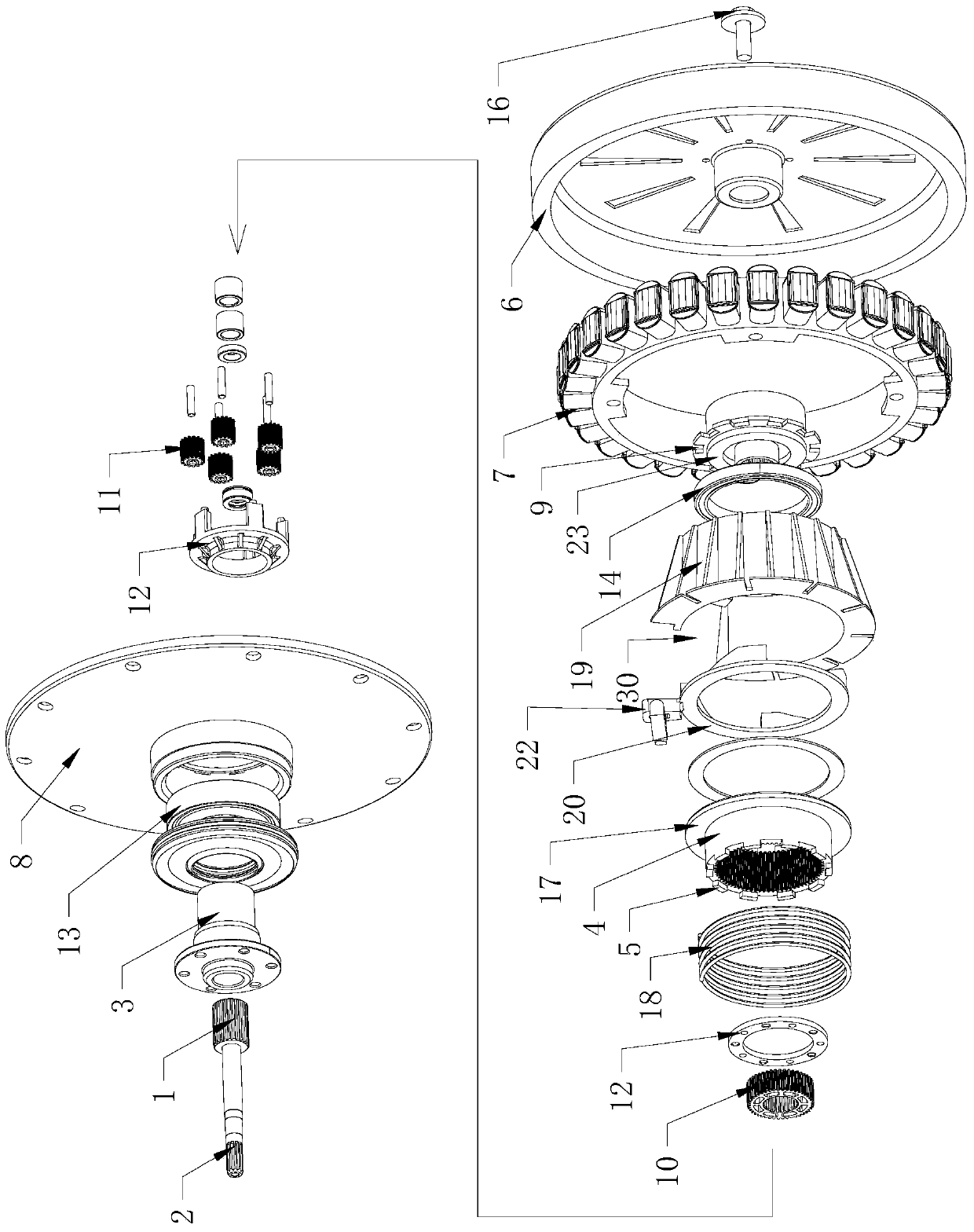
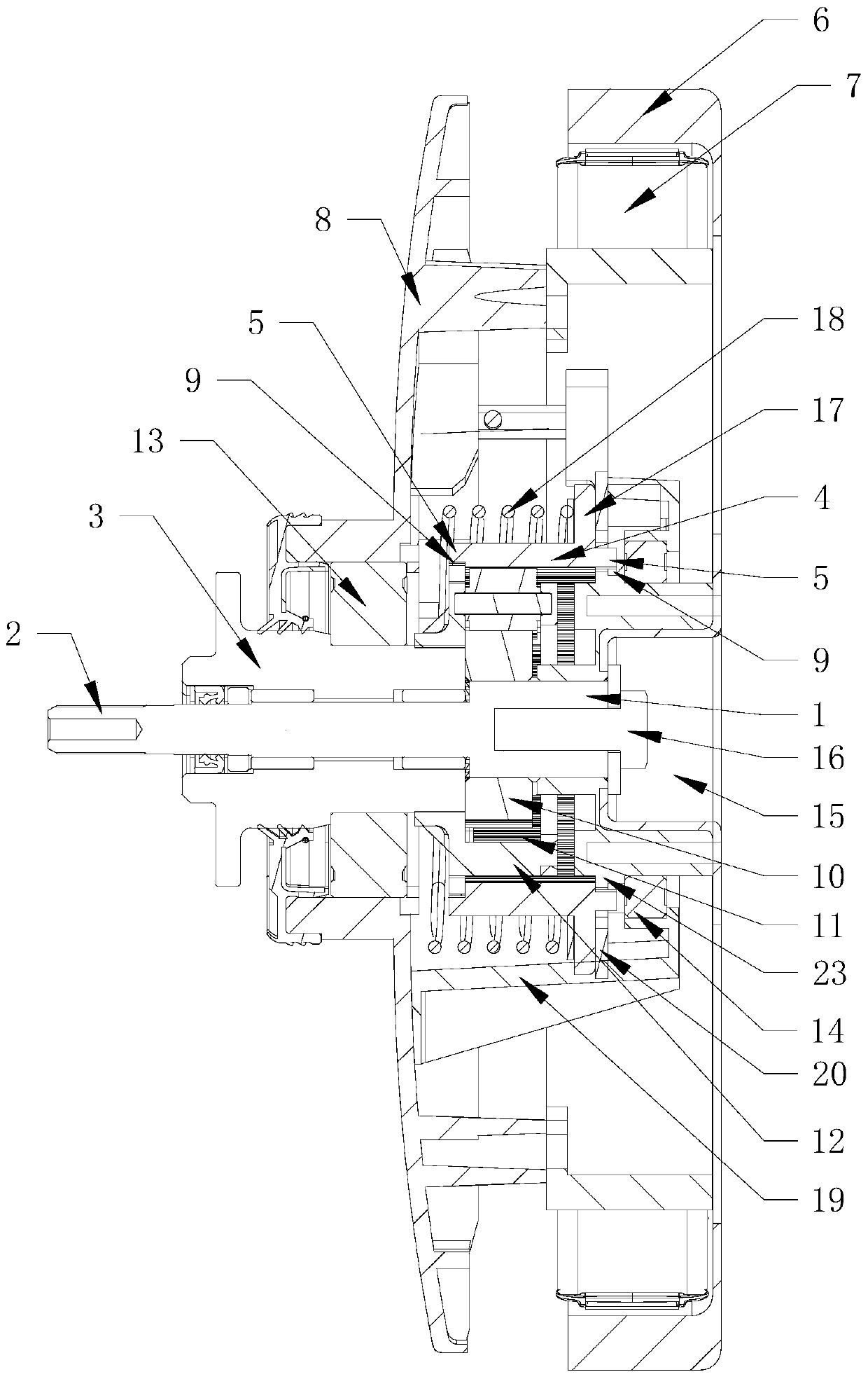
[0038] Such as figure 1 , figure 2 As shown, a washing machine deceleration clutch according to the present invention includes: an input shaft 1, a deceleration device, a clutch device, an output shaft 2 and an output shaft sleeve 3, and the clutch device is arranged on the peripheral periphery of the deceleration device, and on the input shaft The projections on the straight line are at least partially overlapped, and the clutch device at least includes a clutch sleeve that can move axially, and the clutch sleeve is the ring gear 4 of the reduction gear, and the structure of the ring gear 4 that moves axially and in different states connected to control different output states of the output shaft 2 and the output sleeve 3, and the ring gear 4 meshes with at least part of the gears in the reduction gear.

[0039] If the above-mentioned washing machine is a vertical bucket pulsator washing machine, the output shaft 2 is connected to the pulsator, and the output bushing 3 is c...

Embodiment 2

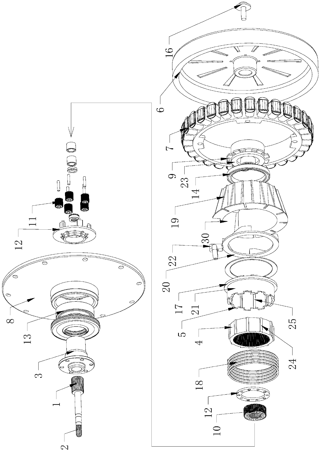
[0072] Such as image 3 , Figure 4 As shown, a washing machine deceleration clutch according to the present invention includes: an input shaft 1, a deceleration device, a clutch device, an output shaft 2 and an output shaft sleeve 3, and the clutch device is arranged on the circumferential periphery of the deceleration device, and the clutch The device at least includes a clutch sleeve 21 that can move axially, and the clutch sleeve 21 is arranged outside the ring gear 4 of the deceleration device, and is connected with the ring gear 4 in an axially relative sliding and circumferentially non-rotatable manner. The shaft sleeve 21 moves axially so that the ring gear 4 is connected to structures in different states through the clutch sleeve 21 to control the different output states of the output shaft 2 and the output sleeve 3. The ring gear 4 is connected to at least part of the reduction gear. gears meshing.

[0073] If the above-mentioned washing machine is a vertical bucke...

Embodiment 3

[0106] A washing machine having the deceleration clutch described in the first or second embodiment above, the washing machine is a pulsator washing machine or a drum washing machine.


PUM


Abstract

The invention relates to a decelerating clutch of a washing machine and the washing machine. The decelerating clutch comprises an input shaft, a decelerator, a clutch device, an output shaft and an output shaft sleeve. The clutch device is at least partially arranged on the periphery of the decelerator in a circumferential direction and at least comprises a clutch shaft sleeve. The clutch shaft sleeve is an inner gear ring of the decelerator which axially moves and is used for controlling different output states of the output shaft and the output shaft sleeve. The decelerating clutch of the washing machine and the washing machine have following beneficial effects: the clutch device is arranged on the periphery of the decelerator so that the part of axial space independently occupied by a conventional clutch device can be saved; an overall height of the decelerating clutch is decreased; the size of the washing machine is decreased with the washing volume changed; or, the washing volume is increased with the size of the washing machine unchanged.

Description

technical field [0001] The invention relates to the field of washing machines, in particular to a washing machine deceleration clutch and a washing machine with the deceleration clutch. Background technique [0002] Washing machines are household appliances commonly used in people's daily life. They are installed in different ways and can be divided into drum washing machines and pulsator washing machines. A drum washing machine generally includes an outer tub, a drum and a motor, and the motor drives the drum to rotate in the outer tub to wash or dehydrate the clothes. Present drum washing machines simply utilize the rotation of the drum for washing, and only use the lifting ribs in the drum to lift and drop the laundry to beat the clothes for washing, so it is difficult to obtain excellent washing effect. The current drum washing machine also has a pulsator in the drum, and the pulsator and the drum are respectively driven by independent motors to optimize the washing eff...

Claims


Application Information

Patent Timeline
Patent Type & Authority Patents(China)
IPC IPC(8): D06F37/30
Inventor 迟宗锐肖磊栾厚利李全德杜会防陈志
Owner QINGDAO HAIER WASHING MASCH CO LTD
Features
  • R&D
  • Intellectual Property
  • Life Sciences
  • Materials
  • Tech Scout
  • Unparalleled Data Quality
  • Higher Quality Content
  • 60% Fewer Hallucinations
Learn More