Needle tooth cycloid speed reducer

A cycloidal reducer and pin-tooth technology, which is applied to gear transmissions, elements with teeth, belts/chains/gears, etc., can solve problems such as high production costs, achieve convenient manufacturing, ensure force-bearing effect, Structure setting simple effect

Active Publication Date: 2016-02-03
QUANTA MACHINERY CO LTD
View PDF7 Cites 9 Cited by
  • Summary
  • Abstract
  • Description
  • Claims
  • Application Information

AI Technical Summary

Problems solved by technology

However, it has been proved that simply doing this cannot fully achieve the purpose, and the resulting high production cost also ma

Method used


Image

  • Needle tooth cycloid speed reducer
  • Needle tooth cycloid speed reducer
  • Needle tooth cycloid speed reducer

Examples


Embodiment Construction

[0028] The present invention will be described in detail below in conjunction with various embodiments shown in the drawings. However, these embodiments do not limit the present invention, and any structural, method, or functional changes made by those skilled in the art according to these embodiments are included in the protection scope of the present invention.

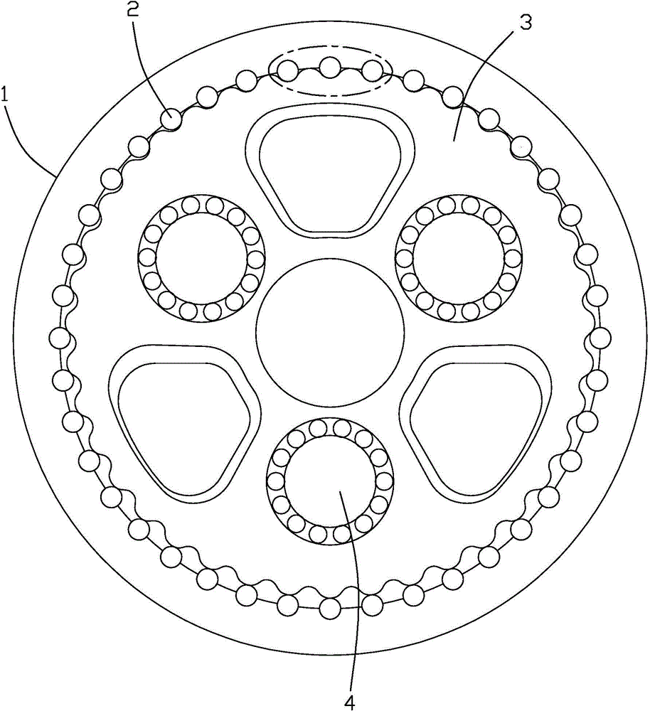
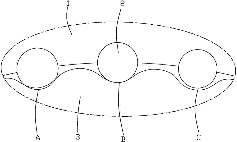
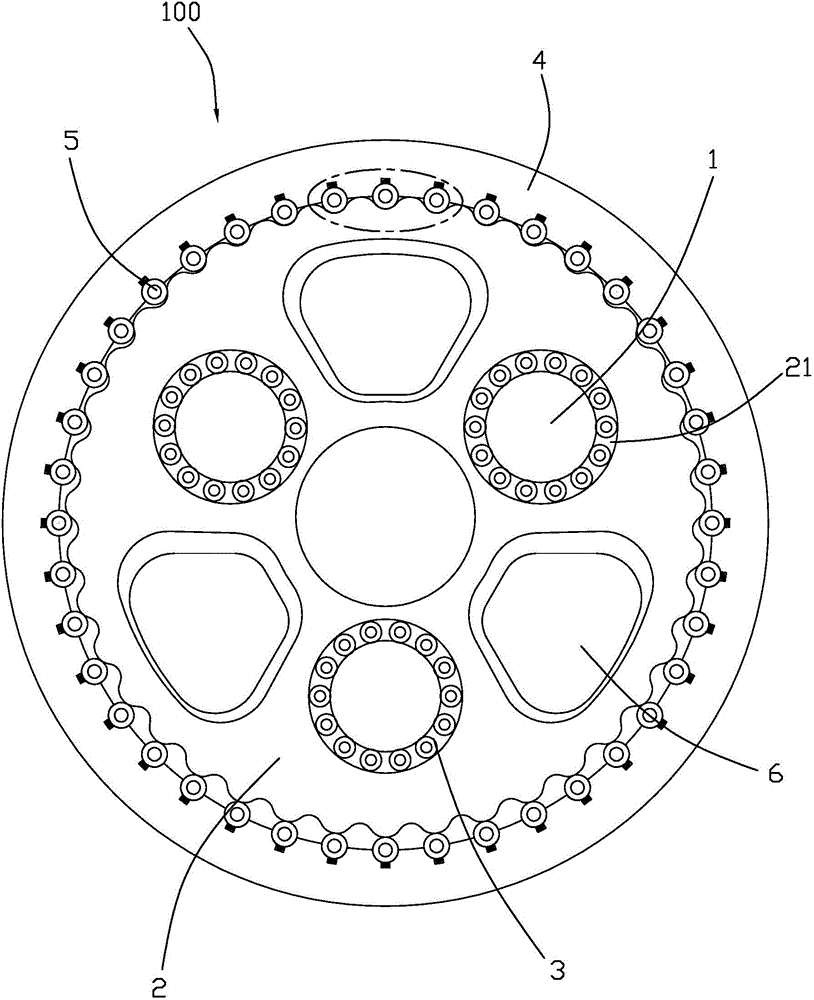
[0029] Please refer to Figure 3 to Figure 7 Shown is a preferred embodiment of the pin cycloid reducer 100 of the present invention. The pin-toothed cycloid reducer 100 includes an input shaft (not shown) located in the middle to connect to a servo motor (not shown), an input gear (not shown) integrally formed at the end of the input shaft, and an input gear (not shown) that is meshed with the input gear The surrounding planetary gears (not shown), the crankshaft 1 fixed to the planetary gears, the cycloidal disk 2 cooperating with the crankshaft 1, and the roller bearing 3 cooperatingly arranged between the crank...


PUM


Abstract

The invention provides a needle tooth cycloid speed reducer. The needle tooth cycloid speed reducer comprises a cycloid disc, a needle tooth shell, and a needle tooth component clamped between the cycloid disc and the needle tooth shell. The needle tooth component comprises multiple elastic rolling column combinations uniformly distributed in the peripheral direction of the inner side of the needle tooth shell. The elastic rolling column combinations comprise elastic rolling columns, and elastic elements clamped between the elastic rolling columns and the needle tooth shell in the radial direction of the needle tooth shell.

Description

technical field [0001] The invention relates to the technical field of reducers, in particular to a pin-toothed cycloid reducer. Background technique [0002] Pin-toothed cycloidal reducers have been widely used as transmission devices for industrial robots. In particular, the pin-toothed cycloid reducer represented by the RV reducer has become the most important part of the robot system due to its compact structure and strong transmission capacity. Please refer to figure 1 As shown, the RV pin cycloid reducer is mainly composed of pin gear housing 1, pin teeth 2, cycloid disc 3, eccentric shaft 4 and so on. The rotation of the eccentric shaft 4 drives the cycloidal disc 3, so that the cycloidal disc 3 performs a cycloidal motion on the needle teeth 2 to push the cycloidal disc 3 forward. Theoretically, there can be nearly 1 / 3 of the number of teeth 2 cooperating with the cycloid disc 3 at the same time, that is to say, there are so many needle teeth 2 that can bear force...

Claims


Application Information

Patent Timeline
IPC IPC(8): F16H1/32F16H55/14F16H55/18
CPCF16H1/2863F16H1/32F16H55/14F16H55/18F16H2001/323F16H2001/327
Inventor 孙子建刘毅郑美珠
Owner QUANTA MACHINERY CO LTD
Why Eureka
Try Eureka