A lighting fixing module for a colored metal model and a manufacturing method thereof

A color metal, fixed module technology, applied in the direction of light source fixation, fixed lighting device, light guide of lighting system, etc., can solve the problems of increasing energy consumption, unable to meet the model surface, increasing manufacturing cost, etc., to improve the grade and increase the appearance. Authenticity, the effect of reducing its own energy consumption

Active Publication Date: 2017-10-24
陈琰
View PDF4 Cites 0 Cited by
  • Summary
  • Abstract
  • Description
  • Claims
  • Application Information

AI Technical Summary

Problems solved by technology

The disadvantage is that each light-emitting point on the surface of the model needs to be installed with an LED lamp bead, and each lamp bead needs a corresponding wire to provide power
It is more suitable for models with few light-emitting points on the surface and enough space inside. LED lamp beads, which are commonly used as point light sources, cannot meet the needs of a large number of models on the surface and intensive lighting effects due to their own size limitations.
It is even more impossible to arrange and install densely along the contour of the surface light source
The increase in the number of LED lamp beads installed will cause a large number of wires inside the model, which will increase the manufacturing cost and increase the energy consumption.

Method used


Image

  • A lighting fixing module for a colored metal model and a manufacturing method thereof
  • A lighting fixing module for a colored metal model and a manufacturing method thereof
  • A lighting fixing module for a colored metal model and a manufacturing method thereof

Examples


Embodiment 1

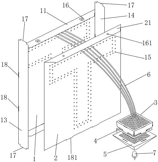
[0035] Embodiment 1: A lighting fixing module.

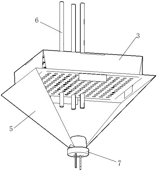
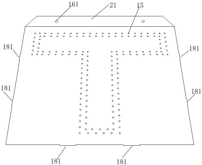
[0036] Such as Figure 1 to Figure 7 As shown, it includes an optical fiber holder A, an optical fiber holder B, a reflector 5, an optical fiber 6 and an LED light source 7. The optical fiber holder A includes a clip AA1 and a clip AB2, and the clip AA1 and the clip AB2 are provided with Optical fiber hole 15, clip AA1 is provided with upper flap 11, lower flap 12, left flap 13 and right flap 14, upper flap is provided with nut positioning groove plus screw hole 16, lower flap 12, left flap 13 and The right flange 14 is provided with a card slot E18, the clip AB2 is provided with an upper flange 21, and the upper flange 21 is provided with a screw hole 161 matching the nut positioning groove and the screw hole 16 provided on the upper flange 11 of the clip AA1, The lower part and the left and right edges are provided with buckles E181 that match the card slots E18 of the lower fold 12, left fold 13 and right fold 14 of the clip...

Embodiment 2

[0038] Embodiment 2: The production of a luminous metal cube model using a lighting fixture module.

[0039] (1) Use 3DS MAX software to import the sorted 3D digital model of the cube. The cube is 200mm long, 200mm wide, and 200mm high.

[0040] (2) Select the cube 3D digital model, right-click, select "Convert to Editable Poly", convert it to Editable Poly, select "Polygon" in the "Editable Poly" modifier in the upper right corner of the window, and select "Polygon" in the cube Press the left button on the surface of the 3D digital model, select the face where the light needs to be installed and execute the "separate" command. make it a separate object.

[0041] (3) Click the "Create" button in the upper right corner of the window, select "Graphics", "Spline"; then right-click on the "Snap Switch" at the top of the window, and set "Top Tick ​​"Multiple" and "Surface"; then close the settings, click "Snap Switch" to enable the capture function; use the "Line" tool of "Spline...

Embodiment 3

[0070] Embodiment 3: Fabrication of a luminous metal triangular prism model using a lighting fixture module.

[0071] (1) Use 3DS MAX software to import the sorted 3D digital model of the triangular prism. The height of the triangular prism is 200mm, the top and bottom are regular triangles, and the side length is 200mm.

[0072] (2) Select the 3D digital model of the triangular prism, right-click, and select "Convert to Editable Poly", convert it to an editable polygon, and then select "Polygon" in the "Editable Poly" modifier in the upper right corner of the window, in the Click the left button on the surface of the 3D digital model of the triangular prism, select the face where the light needs to be installed and execute the "Separate" command. make it a separate object.

[0073] (3) Click the "Create" button in the upper right corner of the window, select "Graphics", "Spline"; then right-click on the "Snap Switch" at the top of the window, and set "Top Tick ​​"Many" and ...


PUM


Abstract

The invention relates to a lamp decoration fixing module used for a colored metal model and a manufacturing method of the lamp decoration fixing module. The lamp decoration fixing module comprises an optical fiber clamping tool A used for fixing the light-emitting ends of optical fibers, an optical fiber clamping tool B used for fixing the light incoming ends of the optical fibers, a light reflection cover, the optical fibers and a light source. The optical fiber clamping tool A is close to the basic plane provided with a lamp decoration hole. The light reflection cover is connected with the optical fiber clamping tool B. The light source is arranged in the light reflection cover. Drawings used for etching are manufactured through 3D design software and Pepakura Designer software; and metal sheets are etched through the drawings used for etching, and etching pieces are bent upwards and combined to form the lamp decoration fixing module. The single light-emitting source arranged in the model can be transmitted to the corresponding position on the surface of the model through the large number of light guide optical fibers, the procedure of repeatedly installing LED lamp beads and linkage wires in the manufacturing process of the colored metal model is omitted, and therefore it is possible a large number of point light sources are distributed on the surface of the colored metal model.

Description

technical field [0001] The invention belongs to metal model manufacturing technology, in particular to a lighting fixing module for colored metal models and a manufacturing method thereof. Background technique [0002] With the continuous improvement of model making technology and consumer aesthetics. The modeling and surface color painting of model products can no longer meet the needs of consumers. Installing gorgeous lighting effects for models has become a trend in the current model industry. [0003] Installing lighting effects for the model plays an important role in improving the appearance authenticity and product grade of the model. The models on the market generally achieve lighting effects by installing point light sources on the model. The main source of point light source is LED lamp beads. The disadvantage is that each light-emitting point on the surface of the model needs to be installed with an LED lamp bead, and each lamp bead needs a corresponding wire ...

Claims


Application Information

Patent Timeline
Patent Type & Authority Patents(China)
IPC IPC(8): F21S8/00F21V7/10F21V17/10F21V17/12F21V17/16F21V8/00F21Y115/10
CPCF21S8/00F21V7/10F21V17/10F21V17/12F21V17/164
Inventor 陈琰
Owner 陈琰
Why Eureka
Try Eureka