Condenser for refrigerator

A technology for condensers and refrigerators, which is applied in the direction of refrigerators, evaporators/condensers, refrigeration components, etc., and can solve the problem that the extraction position of uncondensed gas cannot be selected, and the retention of uncondensed gas whose heat conduction cannot be determined Position and other issues, to achieve the effect of full performance

Active Publication Date: 2019-05-07
EBARA REFRIGERATION EQUIP & SYST CO LTD
View PDF5 Cites 0 Cited by
  • Summary
  • Abstract
  • Description
  • Claims
  • Application Information

AI Technical Summary

Problems solved by technology

[0008] In this way, in the condenser 2 in which the heat transfer tube group 12 for cooling water and the heat transfer tube group 13 for warm water are housed in one container body 11, when fluids with different temperatures and flow rates flow through the tubes with respect to the two heat transfer tube groups, , it is also conceivable that a part of the refrigerant gas discharged from the compressor and flowed into the condenser passes between the heat transfer tube group 12 for cooling water and the heat transfer tube group 13 for warm water, and the other part passes between the heat transfer tube group 13 for cooling water. 12 and the heat transfer tube group 13 for warm water, since the condition of the refrigerant gas cannot be inferred in detail, it is impossible to determine the location where the uncondensed gas that hinders heat conduction stagnates, so that it cannot be selected for extracting the uncondensed gas. The effective pumping position of

Method used


Image

  • Condenser for refrigerator
  • Condenser for refrigerator
  • Condenser for refrigerator

Examples


Embodiment Construction

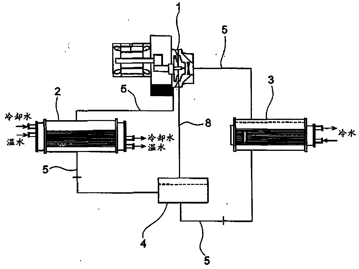
[0026] Below, refer to Figure 1 to Figure 4 Embodiments of the condenser for compression refrigerating machines according to the present invention will be described. exist Figure 1 ~ Figure 4 In , the same reference numerals are attached to the same or corresponding constituent elements, and overlapping descriptions are omitted. In this embodiment, a turbo refrigerator using a turbo compressor is shown as an example of a compression refrigerator, but a compressor using a screw type, reciprocating type, scroll type, or the like may also be used.

[0027] figure 1 It is a schematic diagram showing a refrigerator including a condenser according to the present invention. The refrigerator is a two-way condenser refrigerator. Such as figure 1 As shown, the refrigerator has: a turbo compressor 1, which compresses the refrigerant; a condenser 2, which uses a cooling fluid to cool the compressed refrigerant gas to condense it; an evaporator 3, which uses cold water (by Coolin...


PUM


Abstract

The present invention provides a condenser for a refrigerator. A position for condensed gas, which prevents heat conduction, easy to stay is arranged at the special position of a lower layer of a heat conduction pipe group, so that the condensed gas may be suitably extracted from the staying position. In the condenser for the refrigerator where a heat conduction pipe group (12) for cooling water and a heat conduction pipe group (13) for warm water are stored in the main body of the container (11), a demarcation strip (15) is arranged between the heat conduction pipe group (12) for cooling water and the heat conduction pipe group (13) for warm water and extends in the vertical direction which separates the heat conduction pipe group (12) for cooling water and the heat conduction pipe group (13) for warm water.

Description

technical field [0001] The present invention relates to a condenser for a refrigerator that performs heat exchange between high-pressure refrigerant gas discharged from a compressor and a cooling fluid to condense the refrigerant gas. Background technique [0002] The following double bundle condenser refrigerators are known, wherein the condenser has two condensers including a cooling water condenser and a warm water condenser, the cooling water condenser is always connected to the cooling tower, and the warm water The condenser is used for the heating of warm water for heating. This two-way condenser refrigerator includes a condenser in which a heat transfer tube group for cooling water as a cooling water condenser and a heat transfer tube group for warm water as a warm water condenser are accommodated in a single container body. [0003] Figure 5 It is a schematic longitudinal cross-sectional view showing a conventional condenser in which a heat transfer tube group for ...

Claims


Application Information

Patent Timeline
Patent Type & Authority Patents(China)
IPC IPC(8): F25B39/04
Inventor 平田甲介松田伸隆笠松贡
Owner EBARA REFRIGERATION EQUIP & SYST CO LTD
Why Eureka
Try Eureka