Coupled fiber grating wide-range intelligent high-strength steel wire and manufacturing method thereof
A technology of fiber grating and high-strength steel wire, which is applied to measuring devices, optical devices, instruments, etc., can solve the problems of reducing the monitoring accuracy of fiber grating and limiting the monitoring range of fiber grating, so as to avoid adverse effects, improve accuracy and persuade strength, the effect of improving the degree of adhesion
- Summary
- Abstract
- Description
- Claims
- Application Information
AI Technical Summary
Problems solved by technology
Method used
Image
Examples
Embodiment 1
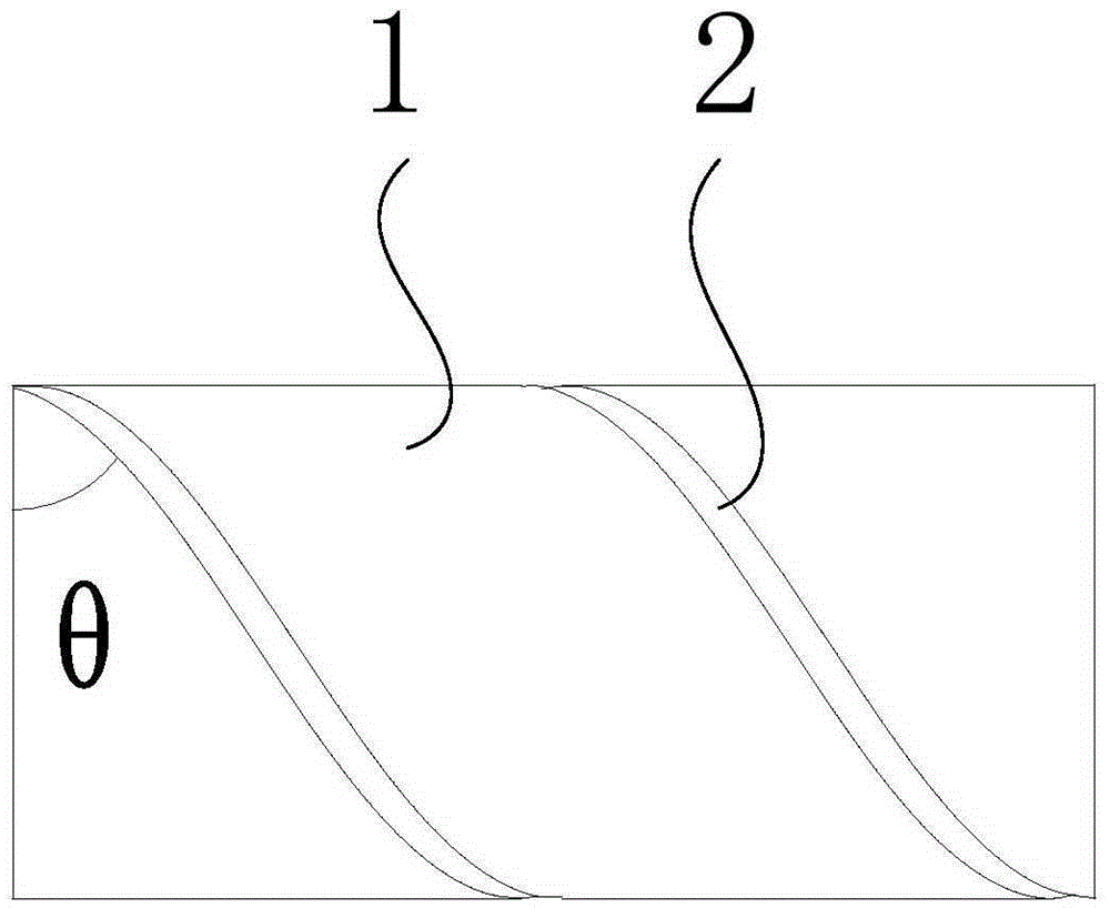
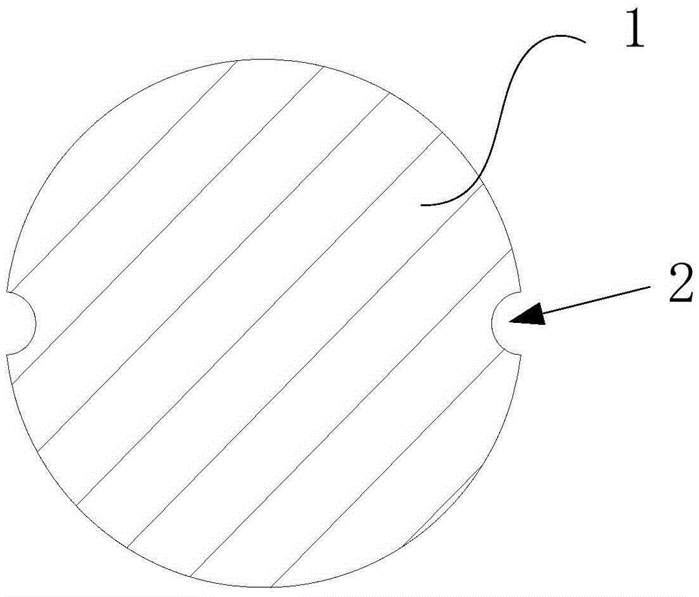
[0035] Such as Figure 1-Figure 5 As shown, this embodiment provides a large-range intelligent high-strength steel wire 1 coupled with a fiber grating, on which at least one spiral groove 2 is arranged, and an optical fiber 3 is placed in the groove 2 and is used to cover all The optical fiber protection layer 4 of the optical fiber line 3, the optical fiber line 3 is engraved with a plurality of gratings.
[0036] Specifically, the cross section of the groove 2 is arc-shaped, and its radius is 0.1-0.6 mm.
[0037] In this embodiment, the optical fiber wire 3 and the optical fiber protective layer 4 fill the groove 2 .
[0038] Specifically, the number of two grooves is 1-8.
[0039] In this example, if Figure 5 As shown, the helix angle θ of the groove 2 may be greater than 0° and less than or equal to 90°. In this embodiment, the helix angle θ of the groove 2 is 30°.
[0040] In the present embodiment, the helix angle θ of the groove 2 increases the range of the optical...
Embodiment 2
[0044] This embodiment provides a method for manufacturing a large-range intelligent high-strength steel wire 1 coupled with an optical fiber 3, and the method steps include:
[0045] Step 1: Open a spiral groove 2 on the steel wire;
[0046] Step 2: Stretching the steel wire, the tensile stress is between 0 and 1860MPa;
[0047] Step 3: apply the optical fiber wire 3 adhesive in the groove 2, and paste the optical fiber wire 3 engraved with the grating in the groove 2;
[0048] Step 4: placing an optical fiber protection layer 4 for covering the optical fiber wire 3 in the groove 2 .
[0049] In this embodiment, after the optical fiber 3 is wound, the middle wire in the steel strand or a steel wire of the steel wire bundle cable is kept stretched for a period of time until the adhesive of the optical fiber 3 takes effect.
[0050] In this embodiment, the cross-section of the groove 2 is arc-shaped, and its radius is 0.1-0.6mm; the number of the groove 2 is 1-8; the helix an...
PUM
| Property | Measurement | Unit |
|---|---|---|
| Radius | aaaaa | aaaaa |
| Helix angle | aaaaa | aaaaa |
| Tensile stress | aaaaa | aaaaa |
Abstract
Description
Claims
Application Information
 - R&D
- Intellectual Property
- Life Sciences
- Materials
- Tech Scout
- Unparalleled Data Quality
- Higher Quality Content
- 60% Fewer Hallucinations
Browse by: Latest US Patents, China's latest patents, Technical Efficacy Thesaurus, Application Domain, Technology Topic, Popular Technical Reports.
© 2025 PatSnap. All rights reserved.Legal|Privacy policy|Modern Slavery Act Transparency Statement|Sitemap|About US| Contact US: help@patsnap.com


