Backlight module and liquid crystal display equipment

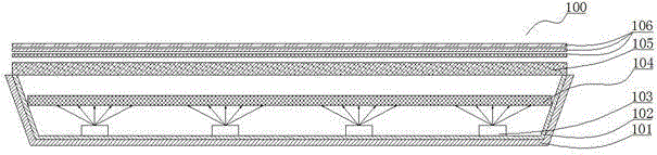
A backlight module and liquid crystal display technology, applied in optics, nonlinear optics, instruments, etc., can solve the problems of low utilization rate of the quantum dot film 104, not being able to irradiate part of the upper part of the quantum dot film 104, and limited excitation range, etc. Achieve the effect of improving the utilization rate and excitation efficiency and expanding the excitation range

Inactive Publication Date: 2016-02-03
HISENSE VISUAL TECH CO LTD
View PDF14 Cites 23 Cited by
  • Summary
  • Abstract
  • Description
  • Claims
  • Application Information

AI Technical Summary

Problems solved by technology

The luminous angle of the blue LED light-emitting chip 103 is a fixed value, and its emitted light is similar to a Lambertian radiator, resulting in a limited excitation range on the quantum dot film 104, causing the light of the LED light-emitting chip 103 to not irradiate on the quantum dot film 104 In some areas, local quantum dots in the quantum dot film 104 are not excited, the overall utilization rate of the quantum dot film is low, and the excitation effect is poor
Exemplarily, the light-emitting angle of the LED light-emitting chip 103 is 120°, and the range of its emitted light is as figure 1 As shown, the excitation range of light emitted by a single LED light-emitting chip 103 on the quantum dot film 104 is as follows figure 1 As shown, there are a plurality of unexcited regions on the quantum dot film 104, resulting in low utilization rate of the quantum dot film 104 and poor excitation effect.

Method used


Image

  • Backlight module and liquid crystal display equipment
  • Backlight module and liquid crystal display equipment
  • Backlight module and liquid crystal display equipment

Examples


Embodiment Construction

[0023] The following will clearly and completely describe the technical solutions in the embodiments of the present invention with reference to the accompanying drawings in the embodiments of the present invention. Obviously, the described embodiments are only some, not all, embodiments of the present invention. Based on the embodiments of the present invention, all other embodiments obtained by persons of ordinary skill in the art without making creative efforts belong to the protection scope of the present invention.

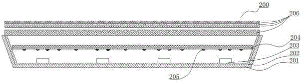
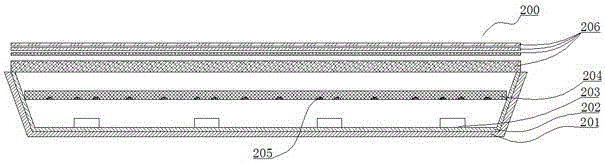
[0024] An embodiment of the present invention provides a backlight module, such as Figure 2~Figure 6 As shown, the backlight module provided by the embodiment of the present invention will be described in detail below with reference to the accompanying drawings. The backlight module provided by the embodiment of the present invention not only includes Figure 2~Figure 6 In addition to the structure shown, it also includes at least a main board, a power board...


PUM

PropertyMeasurementUnit
angleaaaaaaaaaa
reflectanceaaaaaaaaaa

Abstract

The invention discloses a backlight module and liquid crystal display equipment and relates to the technical field of liquid crystal display. By means of the backlight module and the liquid crystal display equipment, the utilization rate of quantum dot materials in the backlight module can be effectively improved, and stimulation efficiency of the quantum dot materials in the backlight module is improved. The backlight module comprises a base plate, LED light-emitting chips and a quantum dot packaging layer, and the LED light-emitting chips are arranged on the inner side of the base plate; the quantum dot packaging layer is arranged above the LED light-emitting chips, and a gap is formed between the quantum dot packaging layer and the LED light-emitting chips, reflection net points are formed in the positions, located on one sides of the LED light-emitting chips, of the quantum dot packaging layer, the transmission path of part of light rays emitted by the LED light-emitting chips is changed, then the quantum dot materials are stimulated, the stimulation range of the light rays emitted by the LED light-emitting chips on the quantum dot packaging layer is broadened, and the utilization rate of the quantum dot materials in the backlight module is raised, and the stimulation efficiency of the quantum dot materials is improved. The backlight module is applied to the liquid crystal display equipment.

Description

technical field [0001] The invention relates to the technical field of liquid crystal display, in particular to a backlight module and a liquid crystal display device. Background technique [0002] A liquid crystal display device includes an LCD liquid crystal panel for displaying image content and a backlight module for providing a white light source to the LCD liquid crystal panel. The color gamut range of the white light source of the backlight module determines the color gamut range in which the liquid crystal display presents image content. In order to improve the color gamut range of the white light source, a blue LED chip is used to excite the quantum dot material to emit green light and red light, and the green light, red light and unexcited blue light are mixed to form a white light source. [0003] example, such as figure 1 As shown, a typical structural diagram of a direct type backlight module in the prior art, refer to figure 1 As shown, the direct type backl...

Claims


Application Information

Patent Timeline
Patent Type & Authority Applications(China)
IPC IPC(8): G02F1/13357
CPCG02F1/1336G02F1/133603G02F1/133605G02F1/133614
Inventor 宋志成
Owner HISENSE VISUAL TECH CO LTD
Why Eureka
Try Eureka