A tandem white organic light emitting device

An organic light-emitting device, white technology, applied in the direction of organic semiconductor devices, electric solid devices, semiconductor devices, etc., can solve the problems of high voltage and difficult preparation, and achieve the effects of improving efficiency, reducing equipment costs, and reducing voltage

Active Publication Date: 2018-05-01
GUAN YEOLIGHT TECH CO LTD
View PDF5 Cites 0 Cited by
  • Summary
  • Abstract
  • Description
  • Claims
  • Application Information

AI Technical Summary

Problems solved by technology

[0004] Therefore, the technical problem to be solved by the present invention lies in the problem of high voltage and difficult preparation in the prior art, and further provides a series white organic light-emitting device, since the first hole transport layer is evaporated by a linear evaporation source to form a continuous concentration gradient structure, reducing the number of evaporation sources in the evaporation chamber, greatly reducing the hole injection barrier, which can significantly reduce the voltage of the device and improve efficiency

Method used


Image

  • A tandem white organic light emitting device
  • A tandem white organic light emitting device
  • A tandem white organic light emitting device

Examples


Embodiment 1

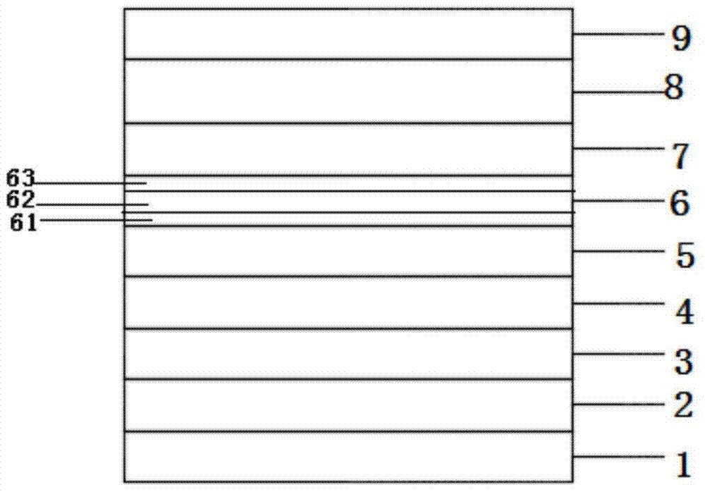
[0031] Such as figure 1 As shown, a tandem white organic light-emitting device of the present invention includes a substrate, and a first electrode layer 1, several blue-light fluorescent light-emitting units, several charge generation layers, several phosphorescent light-emitting units with a light-emitting wavelength greater than 500 nm, and a first electrode layer 1 are stacked. Two electrode layers 9; figure 1 The blue fluorescent light-emitting unit and the phosphorescent light-emitting unit of the serial white organic light-emitting device shown are one layer respectively.

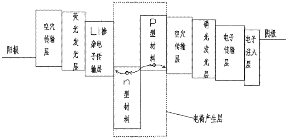
[0032] An n-type charge generation layer 5 made of an n-type material is arranged between the adjacent blue fluorescent light-emitting units and phosphorescent light-emitting units; Phosphorescent emitting layer.

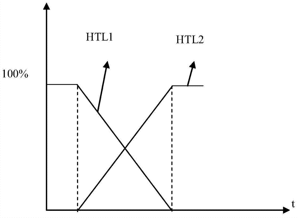
[0033] The phosphorescent light-emitting unit includes a first hole transport layer 6, a phosphorescent light-emitting layer 7 and a first electron transport layer 8; the first hole tran...

Embodiment 2

[0066] Such as Figure 4 As shown, a tandem white organic light-emitting device of the present invention includes a substrate, and a first electrode layer 1, a phosphorescent light-emitting unit, an n-type charge generation layer 5, a blue fluorescent light-emitting unit, an n-type charge generation layer 5, a phosphorescent The light emitting unit and the second electrode layer 9; other structures are the same as those in Embodiment 1. Specifically, a first electrode layer 1, a hole injection layer 10, a first hole material layer 61, a transition layer 62, a second hole material layer 63, a phosphorescent layer 7, and a first electron transport layer are stacked on the substrate. 8. The n-type charge generation layer 5, the second hole transport layer 2, the blue fluorescent light-emitting layer 3, the second electron transport layer 4, the n-type charge generation layer 5, the first hole material layer 61, the transition layer 62, the second Two hole material layers 63 , a ...


PUM


Abstract

The invention relates to a white organic light-emitting device in series, which includes a substrate, and a first electrode layer, a plurality of blue fluorescent light-emitting units, a plurality of charge generation layers, a plurality of phosphorescent light-emitting units and a second electrode layer are stacked, and the adjacent blue fluorescent light-emitting units An n-type charge generation layer made of an n-type material is arranged between the phosphorescent light-emitting unit; the phosphorescent light-emitting unit includes a first hole transport layer, a phosphorescent light-emitting layer and a first electron transport layer; the first hole The transport layer includes a first hole material layer, a transition layer and a second hole material layer; the first hole material layer is in contact with the n-type charge generation layer; the first hole material layer and the n-type The charge generation layers collectively constitute the charge generation layer. Since the material of the first hole transport layer is evaporated by a linear evaporation source to form a continuous concentration gradient structure, the number of evaporation sources in the evaporation chamber is reduced, and the hole injection barrier is greatly reduced, thereby significantly reducing the voltage of the device and improving efficiency.

Description

technical field [0001] The invention relates to the technical field of serial white organic light-emitting devices, in particular to a material for a hole transport layer of a phosphorescent light-emitting unit that is vapor-deposited by a linear evaporation source to form a continuous structure with a concentration gradient. Background technique [0002] A tandem white organic light emitting device includes a charge generation layer sandwiched between two light emitting units. The charge generation layer transports electrons or holes to adjacent light emitting units. However, in the tandem white organic light emitting device, holes or electrons of the charge generation layer may not be transported to adjacent light emitting units. In this case, normal light emission may not be performed in the adjacent phosphorescent light emitting unit or fluorescent light emitting unit. In order to overcome such problems, a hole transport layer having a double-layer structure (including...

Claims


Application Information

Patent Timeline
Patent Type & Authority Patents(China)
IPC IPC(8): H01L51/50H01L51/52
CPCH10K71/16H10K50/156H10K50/19H10K2101/27H10K2101/30Y04S30/12Y02T90/167
Inventor 李曼张国辉朱映光谢静
Owner GUAN YEOLIGHT TECH CO LTD
Why Eureka
Try Eureka