Fuel cell stack assembly device

A fuel cell stack and assembly device technology, which is applied in the direction of fuel cells, fuel cell groups, circuits, etc., can solve problems such as distortion and deformation of the import and export industry, distortion of the stack, and impact on battery performance, so as to ensure orderliness and improve Assembling efficiency and the effect of assembling the stack beautifully

Active Publication Date: 2016-02-03
SHANGHAI INST OF SPACE POWER SOURCES
View PDF7 Cites 12 Cited by
  • Summary
  • Abstract
  • Description
  • Claims
  • Application Information

AI Technical Summary

Problems solved by technology

However, the multi-cell stack uses bipolar plates and electrodes stacked one by one, so the stack is prone to distortion and deformation during the compaction process.
The deformed and twisted stack will be distorted and deformed due to the internal import and export of the stack, which will cause uneven distribution of the medium in and out of the stack, and the performance of the battery will be seriously affected.
This phenomenon is particularly easy to occur during the assembly of metal plate stacks, mainly because the thin metal bipolar plates are only 0.1mm~0.2mm thick, thinner than graphite plates, and are easy to deform, and the stack is also prone to distortion during the assembly process Deformation, put forward higher requirements for the assembly of the stack

Method used


Image

  • Fuel cell stack assembly device
  • Fuel cell stack assembly device
  • Fuel cell stack assembly device

Examples


Embodiment 1

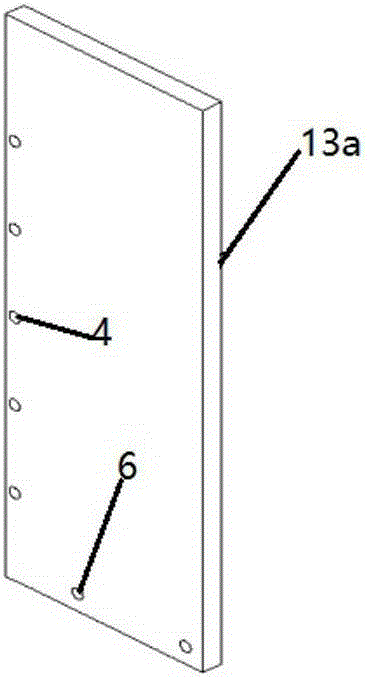
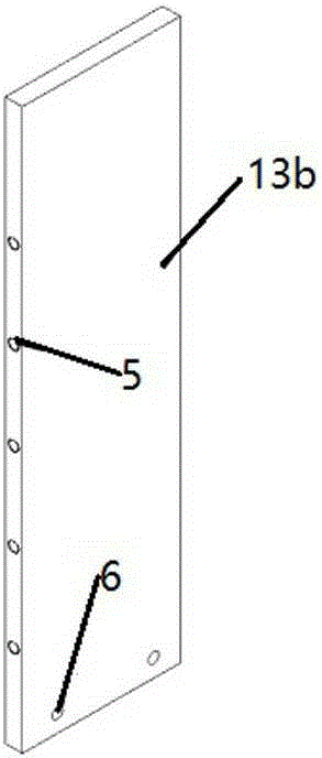
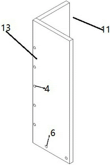
[0040] Such as Figure 1~3 As shown, the two flat plates 13 of the vertical limiting plate 11 can be designed according to the shape of the end plate of the electric stack, and the length can be designed according to the length of the assembled electric stack. Some third through holes 4 of Φ5 or 6 and third threaded holes 5 of M5 or M6 are evenly distributed on the vertical limiting plate 11 . Bolts can be used to connect the two flat plates 13 of the vertical limiting plate 11 through the third through hole 4 and the third threaded hole 5 . The second through hole 6 can fix the vertical limiting plate 11 on the bottom plate fixing plate 3 through bolts.

[0041] Such as Figure 4 As shown, the fixing frame 2 is composed of several long fixing strips 21, and the number of the long strips depends on the shape of the end plate of the fuel cell. For a rectangular end plate, the fixing frame 2 generally adopts four fixing bars 21.

[0042] Such as Figure 5 As shown, there are...

Embodiment 2

[0045] Such as Figure 7 As shown, the bottom plate fixing plate 3 is designed as a fuel cell end plate, and the end plate is circular. In order to increase the contact area between the limiting component 1 and the pole plate as much as possible, and reduce the processing difficulty and cost of the limiting component 1, the limiting component 1 adopts a narrow arc strip. Fix the 6 arc-shaped limiting strips 12 on the bottom plate fixing plate 3, and install the fixed frame 2 at a certain position near the top of the arc-shaped limiting strips 12. In order to enable components such as pole plates to be assembled and combined smoothly, the inner shape of the fixed frame 2 is consistent with the pole plate, and meanwhile, the arc-shaped limiting strip 12 is connected and fixed with the fixed frame 2 by bolts. Then the fuel cell's buffer plate, conductive plate, pole plate, electrode, etc. are vertically installed in the cylinder defined by the above device. Finally, use a press...


PUM


Abstract

The invention discloses a fuel cell stack assembly device which comprises a limiting part, a fixing frame and a baseplate fixing plate, wherein the baseplate fixing plate is arranged below fuel cells; the size of the baseplate fixing plate is the same as that of a fuel cell end plate; the limiting part comprises a plurality of vertical limiting plates or arc-shaped limiting strips which are perpendicular to the baseplate fixing plate; the bottom ends of the vertical limiting plates or the arc-shaped limiting strips are separately fixed with the side edges of the baseplate fixing plate; the upper parts of the vertical limiting plates or the arc-shaped limiting strips are sleeved by the fixing frame for fixing. A fuel cell stack assembled by adopting the device is uniform and looks beautiful; through adoption the device, the fuel cell stack assembly frequency is improved, the operation is simple, and the reliability is higher.

Description

technical field [0001] The invention relates to a proton exchange membrane fuel cell metal bipolar plate assembly device, in particular to a proton exchange membrane fuel cell stack assembly device. Background technique [0002] Proton exchange membrane fuel cell (PEMFC) is a power generation device that converts chemical energy in fuel into electrical energy through chemical reaction. It has the advantages of high power density and low environmental pollution. The dynamic power source has a broad application prospect, which has attracted more and more countries and enterprises' attention. At present, PEMFC has been successfully applied to passenger buses and cars at home and abroad. [0003] The bipolar plate has the functions of isolating and evenly distributing the reaction gas, collecting and exporting current, and connecting individual cells in series. Its materials mainly include metal materials, graphite materials and composite materials. Due to the different mater...

Claims


Application Information

Patent Timeline
Patent Type & Authority Applications(China)
IPC IPC(8): H01M8/2404
CPCH01M8/24Y02E60/50
Inventor 孙毅张伟刘向蒋永伟朱荣杰王涛
Owner SHANGHAI INST OF SPACE POWER SOURCES
Why Eureka
Try Eureka