Hinged type wire connector

A wire connector and connector technology, applied in the direction of adjusting/maintaining mechanical tension, cable suspension device, etc., can solve the problem of not considering the tension bearing capacity of the wiring clip, etc., and achieve simple structure, good tension bearing capacity, and bearing tension capacity Improved effect

Active Publication Date: 2016-02-03
GUANGZHOU PANYU CABLE WORKS
View PDF11 Cites 0 Cited by
  • Summary
  • Abstract
  • Description
  • Claims
  • Application Information

AI Technical Summary

Problems solved by technology

From the above patent application and analysis of other existing technical solutions, it is found that these improvement solutions do not consider the tension bearing capacity of the terminal clamp. In actual use, the terminal clamp is easy to install and disassemble. If it is in some connection fields, it needs to be easy to install. and disassembly, and at the same time need to bear a certain tension, no matter what kind of existing connecting fittings are used, they cannot meet the requirements very well

Method used


Image

  • Hinged type wire connector
  • Hinged type wire connector
  • Hinged type wire connector

Examples


Embodiment 1

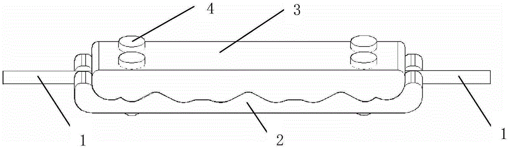
[0038] A hinge-type wire connector, including a connector body 2, a pressing block 3, and a locking device for detachably connecting the connector body 2 and the pressing block 3, and one surface of the connector body 2 is provided with concave and convex pressure lines Correspondingly, one surface of the pressing block 3 is provided with a matching concave-convex crimping structure, the shape of the concave-convex crimping structure is arbitrary, and it can be a wave-shaped undulating structure set on the surface of the connector body and the pressing block , or other structures that make the above-mentioned surface not a horizontal surface in the longitudinal direction; and at least one of the connector body 2 and the pressing block 3 is provided with a limiting structure for preventing the wire from sliding laterally; preferably a wire hole or a wire groove 6, When in use, the wire 1 is set between the concave-convex crimping structure of the connector body 2 and the concavo...

Embodiment 2

[0048] On the basis of the technical solution of the wire binding clip described in embodiment 1, the following improvements have been further made:

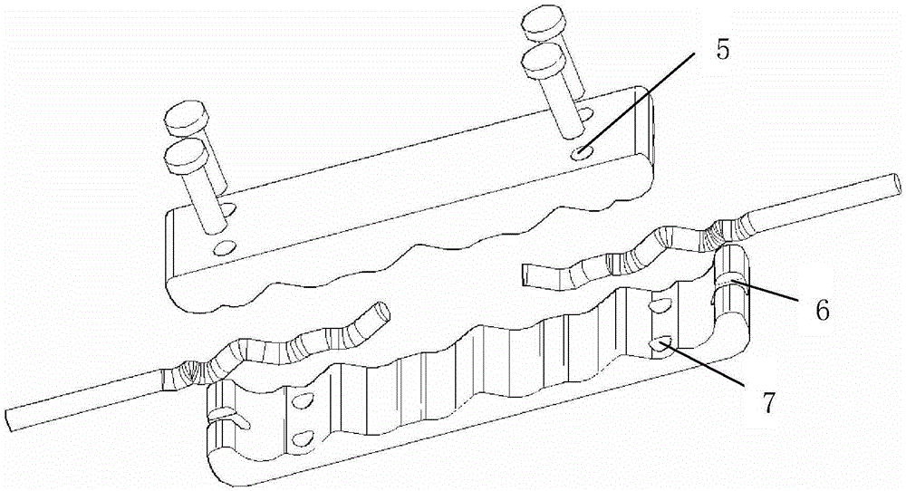
[0049] Such as Figure 6 , 7 As shown in and 10, a pair of wire holes or wire slots 6 are provided on the connector body 2 or the pressing block 3; the pair of wire holes or wire slots 6 can accommodate more than two wires; the two or more The wires are respectively inserted from the wire hole or the wire groove 6 at one end of the connector body 2 or the pressing block 3, and are arranged in more than two corresponding wire insertion grooves 8; the locking device includes more than two locking screws 4 , its position is set on both sides of the wire slot 8;

Embodiment 3

[0051] On the basis of the technical solution of the wire binding clip described in embodiment 1, the following improvements have been further made:

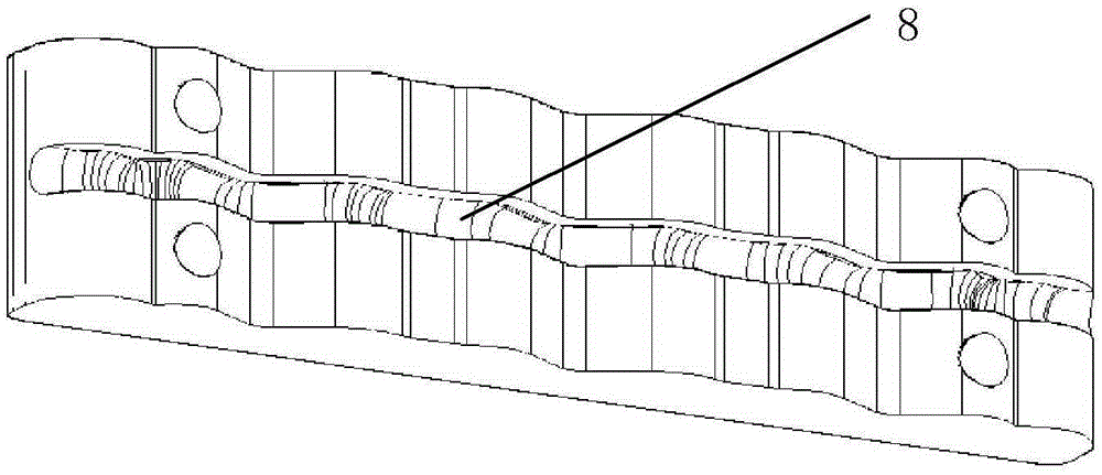
[0052] Such as Figure 8 , 9 As shown in and 11, two or more pairs of wire holes or wire grooves 6 are arranged at intervals on the connector body 2 or the pressing block 3; The wire holes or wire grooves 6 are inserted and set in more than two corresponding wire insertion grooves 8; the locking device includes more than two locking screws 4, and their positions are set on both sides of the wire insertion groove or two wire insertion grooves. between slots.


PUM


Abstract

The invention discloses a hinged type wire connector. The hinged type wire connector comprises connector bodies, pressure blocks, and locking devices for detachable connection with the connector bodies and the pressure blocks. One surface of each connector body is provided with a concave-convex pressing line structure, correspondingly, one surface of each pressure block is provided with a matched concave-convex pressing line structure, and at least one from each connector body and each pressure block is provided with a limiting structure for preventing wires from transversely slipping off. The hinged wire connector provided by the invention is simple in structure, simple to operate, good in mechanical bearing capability, is detachable, can fasten the wire, is good in electrical performance and high in versatility and can realize safe and stable connection.

Description

technical field [0001] The invention belongs to the field of wire connection, and in particular relates to a connecting fitting: a hinge type wire connector. Background technique [0002] In the process of power transmission, the safety and stability of the wire connection is very important. Generally, the connection of the wires is realized by connecting the fittings. The connecting fittings are used for the wires of the overhead power line or the two terminals of the lightning conductor to bear all the tension of the conductor and the lightning conductor or not to bear all the tension. It is also used for the repair of broken strands of wires and lightning conductors. At the same time, as a conductor, the following conditions must be met after wiring: the mechanical strength of the connection point should not be less than 95% of the calculated breaking force of the connected wires. The resistance between two points at the joint should not be greater than the resistance of ...

Claims


Application Information

Patent Timeline
Patent Type & Authority Applications(China)
IPC IPC(8): H02G7/02H02G7/05
Inventor 胡超强尤占山安向阳覃丹王利江卢广业张仕欢申常伟陈雪儿何平
Owner GUANGZHOU PANYU CABLE WORKS
Why Eureka
Try Eureka