
Bipolar pulse signal generating device

A bipolar pulse and pulse signal technology, applied in the field of electrical signal processing, can solve problems such as performance impact and complex structure, and achieve the effects of overcoming parameter constraints, simple circuit structure, and small device size

Active Publication Date: 2016-02-03
SUZHOU INST OF BIOMEDICAL ENG & TECH CHINESE ACADEMY OF SCI
View PDF6 Cites 1 Cited by
  • Summary
  • Abstract
  • Description
  • Claims
  • Application Information

AI Technical Summary

Problems solved by technology

[0004] Therefore, the technical problem to be solved by the present invention is to overcome the defects that the structure of the bipolar pulse signal generating circuit in the prior art is complicated and the performance is affected by the switching circuit components.

Method used


Image

  • Bipolar pulse signal generating device
  • Bipolar pulse signal generating device
  • Bipolar pulse signal generating device

Examples


Embodiment Construction

[0021] The technical solutions of the present invention will be clearly and completely described below in conjunction with the accompanying drawings. Apparently, the described embodiments are some of the embodiments of the present invention, but not all of them. Based on the embodiments of the present invention, all other embodiments obtained by persons of ordinary skill in the art without making creative efforts belong to the protection scope of the present invention.

[0022] In the description of the present invention, it should be noted that the terms "center", "upper", "lower", "left", "right", "vertical", "horizontal", "inner", "outer" etc. The indicated orientation or positional relationship is based on the orientation or positional relationship shown in the drawings, and is only for the convenience of describing the present invention and simplifying the description, rather than indicating or implying that the referred device or element must have a specific orientation, ...


PUM


Abstract

The invention provides a bipolar pulse signal generating device. The bipolar pulse signal generating device comprises a unipolar pulse output unit which is used for outputting a unipolar pulse signal; and a piezoelectric ceramic transformer which comprises an input end, an output end and a piezoelectric body, wherein the input end is connected with the unipolar pulse output unit and is used for receiving the unipolar pulse signal; the piezoelectric body is used for converting the unipolar pulse signal into a bipolar pulse signal; and the output end is used for outputting the bipolar pulse signal.

Description

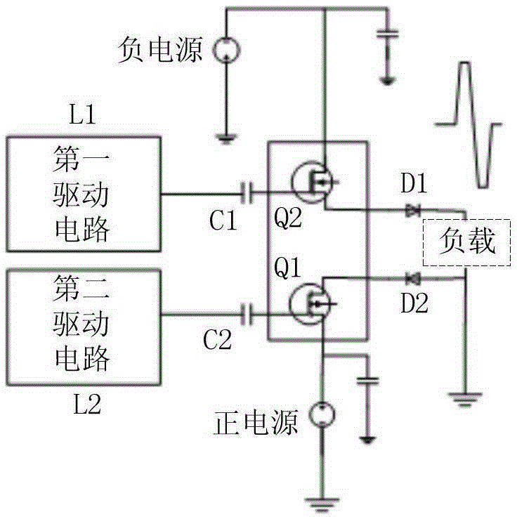
technical field [0001] The invention relates to the field of electrical signal processing, in particular to a bipolar pulse signal generating device. Background technique [0002] The bipolar pulse signal has many uses, and the existing solution is to generate the bipolar pulse signal through a push-pull switch circuit. figure 1 shows a push-pull switching circuit, as figure 1 The circuit shown includes a driving circuit L1, a driving circuit L2, a switching tube Q1, a switching tube Q2, a capacitor C1, a capacitor C2, a diode D1, a diode D2, positive and negative power supplies. In this circuit, L1 and L2 alternately output the drive current, so that Q1 and Q2 alternately connect the positive and negative power supplies in turn, thereby providing bipolar pulse signals to the load. [0003] The problem of the prior art is that the structure of the bipolar pulse signal generating circuit is relatively complicated, and the parameters of devices such as switching tubes in the...

Claims


Application Information

Patent Timeline
Patent Type & Authority Applications(China)
IPC IPC(8): H03K5/13
Inventor 吕铁军邵维维崔崤峣李培洋徐杰
Owner SUZHOU INST OF BIOMEDICAL ENG & TECH CHINESE ACADEMY OF SCI
Learn More