Lightweight electro-mechanical chest compression device

An electromechanical, chest technology, applied in the direction of electrotherapy, therapy, physical therapy, etc., can solve the problems of increasing the weight and size of the system, increasing the setting system and starting compression time, etc., to achieve the effect of weight reduction

Active Publication Date: 2016-02-03
KONINKLJIJKE PHILIPS NV
View PDF10 Cites 6 Cited by
  • Summary
  • Abstract
  • Description
  • Claims
  • Application Information

AI Technical Summary

Problems solved by technology

The need for legs and back panels and a height adjustment mechanism adds weight and size to

Method used


Image

  • Lightweight electro-mechanical chest compression device
  • Lightweight electro-mechanical chest compression device
  • Lightweight electro-mechanical chest compression device

Examples


Embodiment Construction

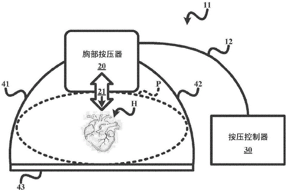
[0016] refer to Figure 1A , the electromechanical CPR apparatus 10 of the present invention provides high quality compressions of the patient P's chest (shown in cross-section). To this end, the CPR apparatus 10 employs a chest compressor 20 , a compression controller 30 and a strap 40 . In operation, the chest compressor 20 is self-supporting on the sternal region of the chest of the patient P, wrapped around the patient P using straps 40 and attached to the sides of the chest compressor 20 . The compression controller 30 provides power and control signals to the chest compressor 20 through the power / control cable 12 so as to apply periodic compression force 21 to the chest of the patient P. The reduced weight of chest compressor 20 facilitates high quality chest compressions for patient P, including chest compressions in the sternal region, to compress the ventricles of patient P's heart H, thereby allowing oxygenated blood to flow to vital organs, and without restriction ...


PUM


Abstract

An electro-mechanical CPR device (10, 11) for applying cardiopulmonary compressions to a chest of a patient employs a chest compressor (20), one or more straps (40) and a compression controller (30). Chest compressor (20) is self- supportable upon the chest of the patient and includes assembly an electric motor (50), a mechanical transmission (60), a linear actuator (70) and a plunger (80) mounted within a housing (100) wherein the linear actuator (70) converts rotational motion generated by the electric motor (50) and the mechanical transmission (60) into linear motion of the plunger (80) for applying a compressive force (21) to the chest of the patient. Strap(s) (40) wrap around the patient and is(are) coupled to chest compressor (20). Compression controller (30) is external to the chest compressor (20) and applies power and controls signals to the electric motor (50).

Description

technical field [0001] The present invention generally relates to electromechanical cardiopulmonary compression ("CPR") devices. Specifically, the present invention relates to an electromechanical CPR apparatus comprising a chest depressor light enough to be self-supportingly placed on a patient's chest and a compression controller for operating the chest depressor to produce High quality compressions for the patient. Background technique [0002] A chest compression cycle consists of a compression phase and a release phase. Specifically, the compression phase involves chest compressions in the sternal region to squeeze the ventricles, thereby allowing oxygenated blood to flow to vital organs, and the release phase involves chest expansion, thereby refilling the ventricles with blood. For high-quality chest compressions, it is important that a sufficient amount of blood is returned to the ventricles during the release phase. However, if a heavier chest compressor is seate...

Claims


Application Information

Patent Timeline
IPC IPC(8): A61H31/00
CPCA61H31/005A61H31/006A61H2201/5061A61H2201/5064A61H31/008A61H2201/1215A61H2201/149A61H2201/1621A61H2201/1664A61H2203/0456A61H2205/084
Inventor N·M·德利斯勒C·沃尔登S·A·乌斯里奇D·W·乔丹三世V·希格利
Owner KONINKLJIJKE PHILIPS NV
Why Eureka
Try Eureka