Jet-flow vacuum machine

A vacuum machine and jet technology, which is applied in the field of vacuuming devices for vacuuming sealed bags, can solve the problems of long-term vacuuming, high power, and high energy consumption

Inactive Publication Date: 2016-02-10
ZHONGSHAN YAXI ENVIRONMENTAL PROTECTION TECH
View PDF6 Cites 0 Cited by
  • Summary
  • Abstract
  • Description
  • Claims
  • Application Information

AI Technical Summary

Problems solved by technology

The manual air pump is more laborious to use, and it takes a long time to achieve the effect of vacuuming
Electric tools are quick to vacuum and have outstanding effects, but many

Method used


Image

  • Jet-flow vacuum machine
  • Jet-flow vacuum machine
  • Jet-flow vacuum machine

Examples


Embodiment Construction

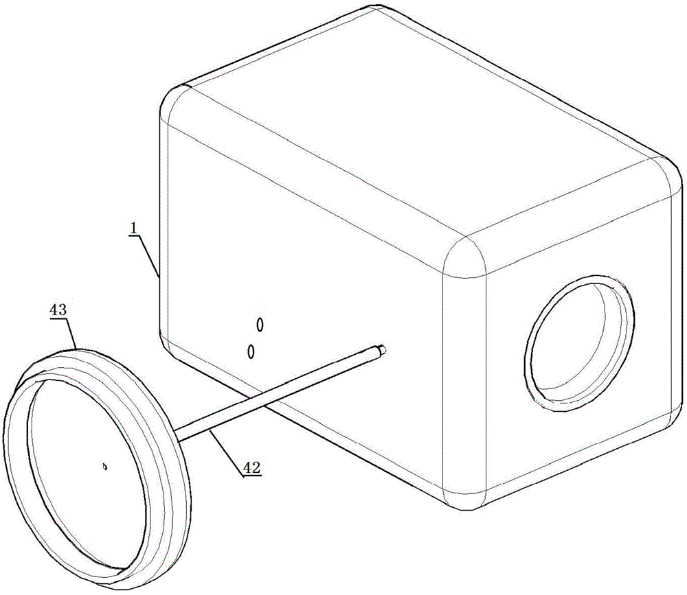
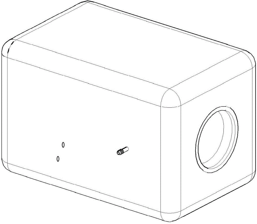
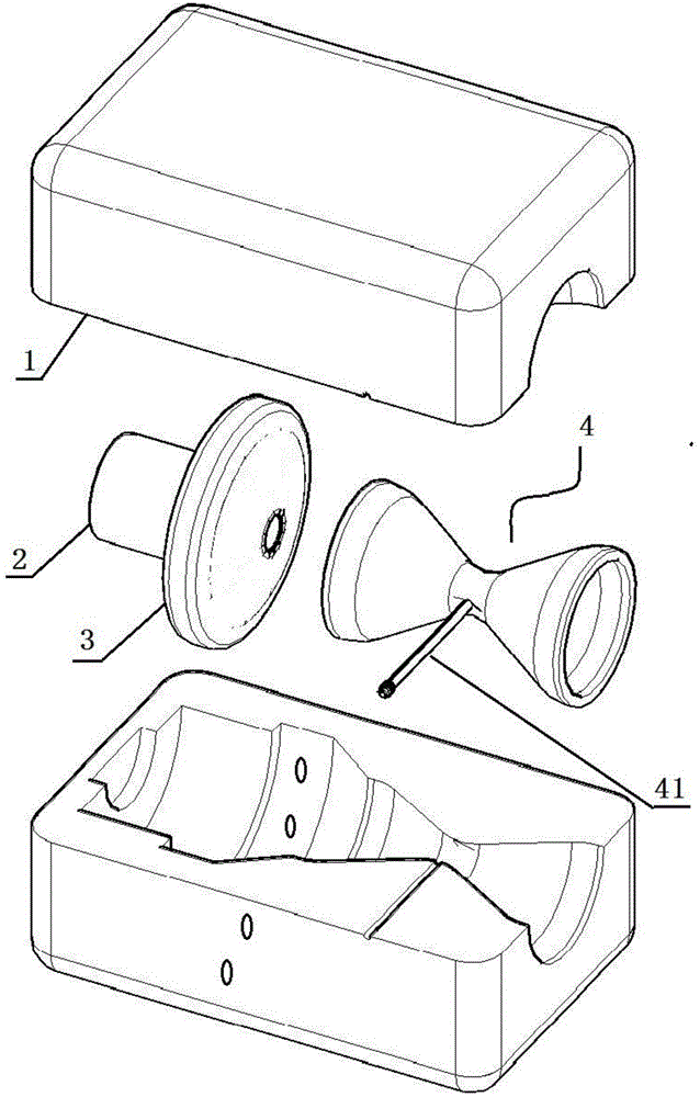
[0015] Such as Figure 1 to Figure 3 As shown, the jet vacuum machine is mainly composed of a casing 1 and a fluidic device placed in the casing. A switch and a power supply / power input interface are provided on the casing. The switch is used to control whether the jetting device is working. The jetting device mainly includes A motor 2, a booster fan 3 and an ejector 4 connected in sequence.

[0016] Such as Figure 4 As shown, the ejector is a Venturi tube structure with two ends large and the middle narrowed, the inlet end of the ejector is sealed and connected with the outlet end of the booster fan 3, and a fixing hole matching the ejector device is provided in the housing. The jet 4 of the jet device is arranged in the fixing hole; the narrow part between the inlet end and the outlet of the jet is provided with a hollow nozzle 41 protruding outwards, and correspondingly, in the fixing hole, there is a Outer nozzle hole matched with the nozzle, the nozzle is placed in the...


PUM


Abstract

The invention relates to a jet-flow vacuum machine. The jet-flow vacuum machine mainly consists of a shell and a jet flow device installed in the shell, wherein the shell is provided with a switch and a power supply/power supply input interface, the switch is used for controlling the jet flow device to work, the jet flow device mainly comprises a motor, a supercharging fan and an ejector, which are sequentially connected with one another. Negative pressure is formed by virtue of rapid flowing of airflow in the ejector, air and vapor in a seal bag are sucked by virtue of the negative pressure, vacuum is formed in the seal bag, and a purpose of rapid drying is realized.

Description

technical field [0001] The invention relates to a device for vacuuming a vacuum-pumping sealed bag, which belongs to the optimization technology of vacuuming the sealed bag. Background technique [0002] Existing vacuum-pumping sealed bags are usually vacuum-pumped by a manual air pump, or vacuum-pumped by an electric vacuum-pumping tool, such as a vacuum cleaner. The manual air pump is more laborious to use, and it takes a long time to achieve the effect of vacuuming. Electric vacuuming tools are quick and effective, but many households are not equipped with electric vacuuming tools, and the power is too high, the energy consumption is also high, and the electric vacuuming tools are too bulky to carry. [0003] Therefore, it is necessary to find a device with less energy consumption, portability and outstanding vacuuming effect. Contents of the invention [0004] The purpose of the present invention is to provide a device with low energy consumption, portability and out...

Claims


Application Information

Patent Timeline
IPC IPC(8): B65B31/04
Inventor 周先平王临川
Owner ZHONGSHAN YAXI ENVIRONMENTAL PROTECTION TECH
Why Eureka
Try Eureka