Clutch device of decelerating clutch and decelerating clutch

A deceleration clutch and clutch device technology, applied in washing devices, other washing machines, textiles and papermaking, etc., can solve problems such as failure of the deceleration clutch clutch device, and achieve the effects of improving reliability, avoiding meshing tooth wear, and improving production efficiency.

Active Publication Date: 2016-02-10
QINGDAO HAIER WASHING MASCH CO LTD
View PDF7 Cites 7 Cited by
  • Summary
  • Abstract
  • Description
  • Claims
  • Application Information

AI Technical Summary

Problems solved by technology

During the long-term working process of the deceleration clutch, it will cause the deceleration clutch clutch device to fail

Method used


Image

  • Clutch device of decelerating clutch and decelerating clutch
  • Clutch device of decelerating clutch and decelerating clutch
  • Clutch device of decelerating clutch and decelerating clutch

Examples


Embodiment 1

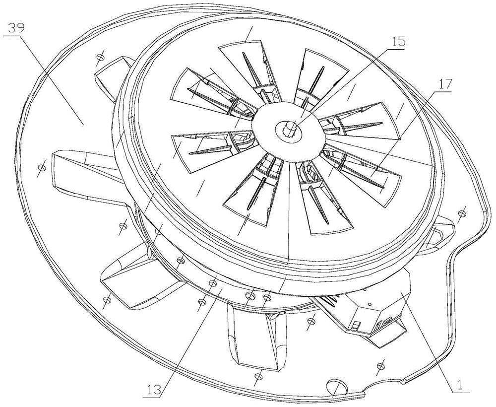
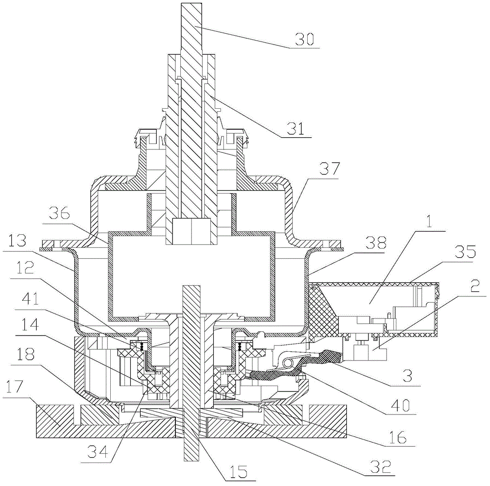
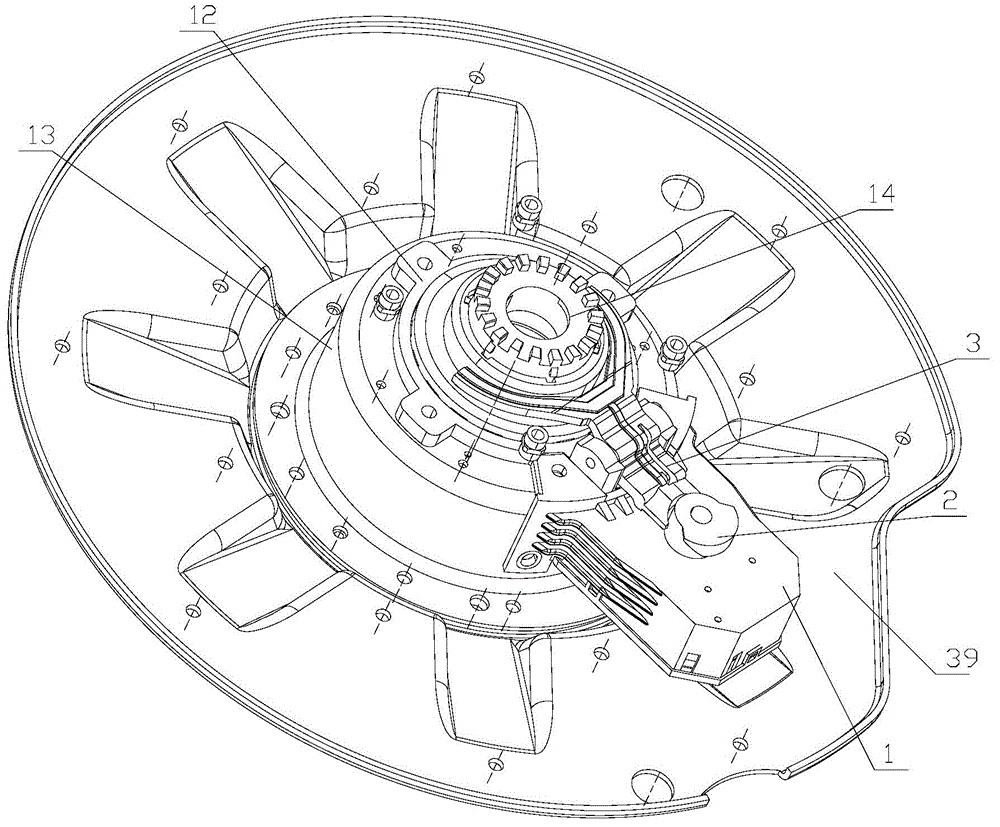
[0039] Such as Figure 3 to Figure 7 as shown in Figure 2-5 As shown, a deceleration clutch clutch driving device described in this embodiment includes a driving motor 1, a driving wheel 2 and a shift fork lever 3, the driving wheel 1 is installed on the output shaft of the driving motor 1, and the circumference of the driving wheel 2 is provided with supports The supporting surface has a height difference in the axial direction. The fork lever 3 is a lever structure with a fixed fulcrum in the middle. The head of the fork lever 3 is a shift fork 6. The shift fork 6 is located below the clutch bushing 14, and the The spring controls the up and down movement of the clutch sleeve 14 together. The tail of the shift fork lever 3 is the driving end 7, and the driving end 7 is provided with a sliding contact surface, which is slidingly matched with the supporting surface; the driving motor 1 drives the driving wheel 2 to rotate, and the tail of the shift fork lever The driving end...

Embodiment 2

[0055] Such as Figure 6 , Figure 8 and Figure 9 As shown, in this embodiment, the upper and lower ends of the clutch sleeve 14 are respectively provided with upper spline teeth 48 meshing with the upper fixed disk and lower spline teeth 49 meshing with the lower dehydration disk. For ease of description, the direction in which the clutch sleeve rotates with the motor rotor 17 is defined as clockwise. The tooth top profile of the upper spline tooth 48 is a slope rising in the clockwise direction; the tooth top profile of the lower spline tooth 49 is a slope descending clockwise. So that. Make the clutch sleeve 14 more smoothly and smoothly mesh when the upper spline teeth 48 and the upper matching spline teeth 50 and the lower spline teeth 49 and the lower matching spline teeth 51 mesh.

[0056] In this embodiment, the lower dehydration tray is composed of a part that is separately set on the top surface of the rotor 17 of the motor or is integrally set with the rotor 17, ...

Embodiment 3

[0064] Such as Figure 8 and Figure 9 As shown, in this embodiment, a clutch bushing, the upper and lower ends of the clutch bushing 14 are respectively provided with upper spline teeth 48 meshing with the upper fixed disk and lower spline teeth 49 meshing with the lower dehydration disk. , At least one of the meshing parts of the upper and lower teeth is provided with a shock-absorbing layer.

[0065] In this embodiment, the shock-absorbing layer is composed of a shock-absorbing sleeve 34 sleeved on the outer wall of the clutch shaft sleeve 14 . The shock absorbing sleeve 34 protrudes from the tooth groove bottom of the lower spline teeth and / or the upper spline teeth, and the shock absorbing sleeve 34 is made of elastic material; preferably, the shock absorbing sleeve 34 is made of It is composed of rubber sleeves that are elastically stretchable and deformable.

[0066] In this embodiment, due to the process of tooth engagement between the clutch sleeve 14 and the lower...


PUM


Abstract

The invention relates to a clutch device of a decelerating clutch and the decelerating clutch. The clutch device comprises a driving motor, a driving wheel, a shifting fork rod and a clutch shaft sleeve, the driving wheel forms a support surface supporting one end of the shifting fork rod, the other end of the shifting fork rod makes limiting contact with the clutch shaft sleeve, an altitude difference is arranged on the support surface formed by the driving wheel, in the process that the driving wheel rotates along with a driving motor shaft, the shifting fork rod is controlled to move through the altitude difference, and the clutch shaft sleeve is driven to move up and down; the upper end and the lower end of the clutch shaft sleeve are provided with an upper spline tooth meshed with an upper fixing plate and a lower spline tooth meshed with a lower dewatering plate respectively, and at least one part of the upper spline tooth and the lower spline tooth is provided with a shock absorption device which provides meshing buffering power. Due to the fact that shock absorption layers are arranged at the upper end and / or the lower end of the clutch shaft sleeve, the collision stress of the clutch shaft sleeve in the meshing process is buffered, abrasion of the spline teeth in the clutch driving process of the clutch device is avoided, and the reliability of the decelerating clutch is improved.

Description

technical field [0001] The invention relates to a speed reduction clutch in the field of washing machines, in particular to a clutch device of the speed reduction clutch. Background technique [0002] The deceleration clutch and the single-phase asynchronous motor of the existing washing machine are installed side by side, and are driven by pulleys and belts. This type of deceleration clutch has low efficiency, high noise, poor practicability, and a high failure rate of the transmission part. Therefore, relevant technical personnel have proposed a technical scheme in which the motor and the clutch are coaxial. [0003] For example, the Chinese patent with application number CN201120257375.8 is a bionic hand-rubbing frequency conversion deceleration clutch for washing machines, which includes a matching lower housing and an input shaft, the lower housing is equipped with a DC brushless motor stator, and the end of the input shaft is connected There is an outer rotor of a bru...

Claims


Application Information

Patent Timeline
IPC IPC(8): D06F37/40
Inventor 张军田云张刚金龚孟虎
Owner QINGDAO HAIER WASHING MASCH CO LTD
Why Eureka
Try Eureka