
High-voltage side shielding shell of high-voltage electronic type current transformer

A technology of current transformer and shielding shell, applied in the direction of transformer/inductor shell, inductor, transformer/inductor components, etc., can solve the problems of narrow frequency band, small dynamic range, high insulation requirements, and achieve the overall light weight, The effect of low processing cost and avoiding heat generation problems

Inactive Publication Date: 2016-02-10
天津市百利纽泰克电气科技有限公司
View PDF5 Cites 2 Cited by
  • Summary
  • Abstract
  • Description
  • Claims
  • Application Information

AI Technical Summary

Problems solved by technology

The shortcomings exposed by traditional electromagnetic transformers such as high insulation requirements, magnetic saturation, ferromagnetic resonance, small dynamic range, and narrow frequency band are difficult to meet the new needs of power systems, and the output signal of current transformer 5A cannot be directly compared with digital measurement Devices and microcomputer protection devices are connected, making it difficult for traditional electromagnetic transformers to meet the development needs of modern power systems such as on-line detection, high-precision fault diagnosis, and computer control and management.

Method used


Image

  • High-voltage side shielding shell of high-voltage electronic type current transformer
  • High-voltage side shielding shell of high-voltage electronic type current transformer

Examples


Embodiment Construction

[0019] In order to further understand the invention content, characteristics and effects of the present invention, the following examples are given, and detailed descriptions are as follows in conjunction with the accompanying drawings:

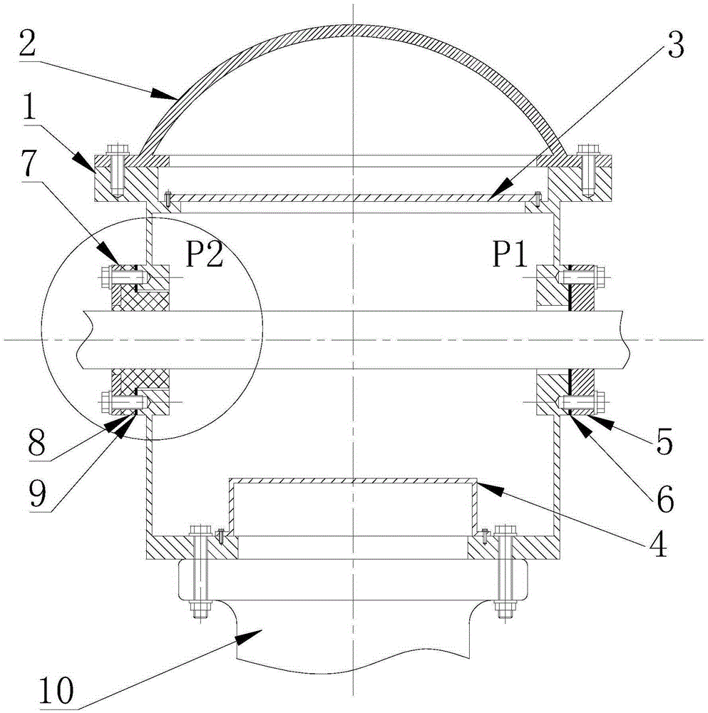
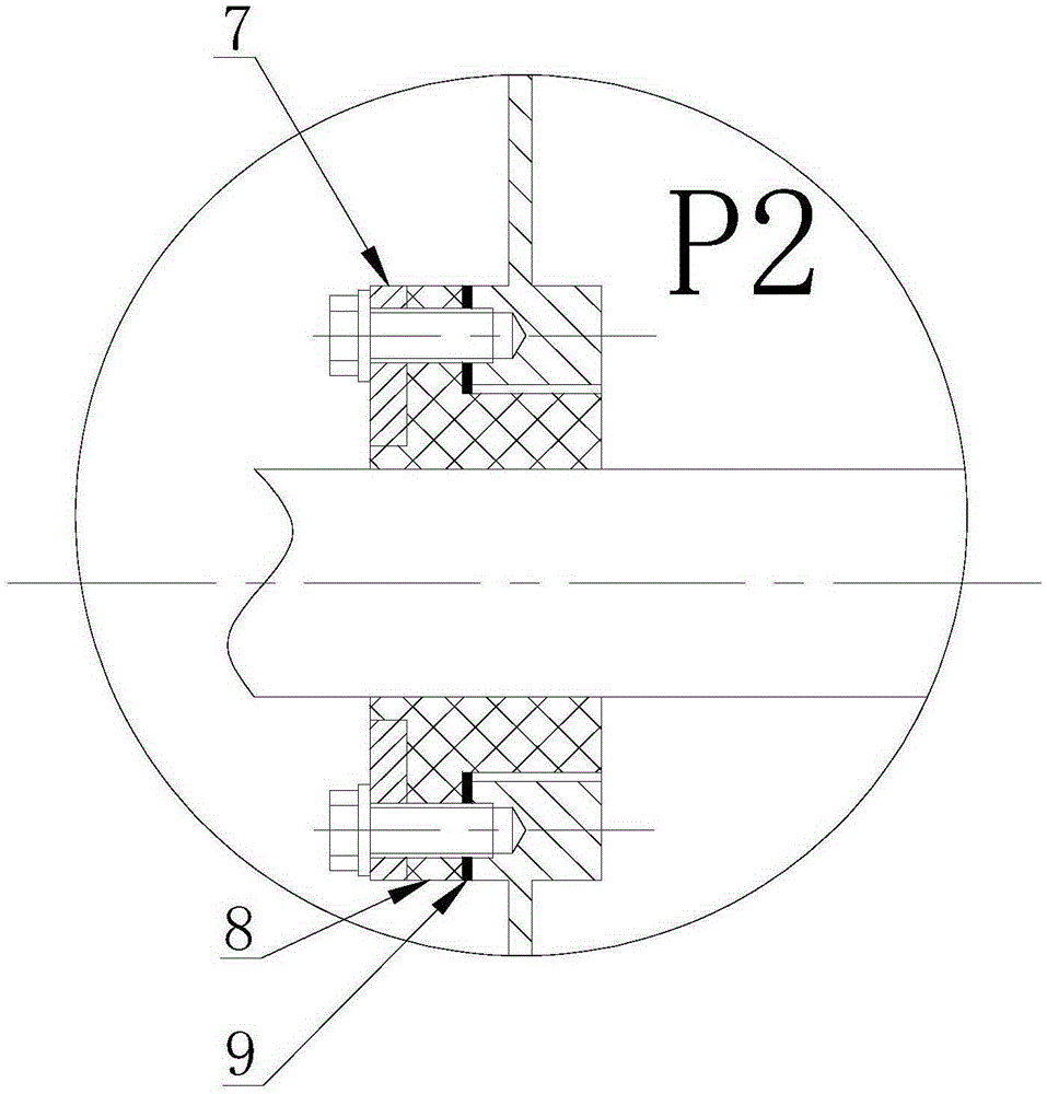
[0020] see figure 1 and figure 2 , a high-voltage electronic current transformer high-voltage side shielding shell, including a shell 1 with openings on the top, bottom, and left and right sides, and a shell cover 2 on the top of the shell, which is located on the top of the shell for supporting The collector support plate 3 of the fixed current signal collector, and the coil support frame 4 located at the bottom of the housing for supporting the fixed current transformer coil; the left and right sides of the housing 1 are respectively opened with P1 and P2 for the primary conductive rod of the current. Two openings, P1 and P2 are provided with screw holes on the outside of the two openings, which are used to install and fix the P1 end stru...


PUM


Abstract

The invention relates to a high-voltage side shielding shell of a high-voltage electronic type current transformer. The high-voltage side shielding shell comprises a shell body, a shell body cover, a collector supporting plate and a coil supporting frame. Openings are reserved in the top, the bottom, the left side and the right side of the shell body respectively. The top end of the shell body is covered with the shell body cover. The collector supporting plate is located on the top of the shell body. The coil supporting frame is located at the bottom of the shell body. The opening P1 and the opening P2 are formed in the left side and the right side of the shell body respectively. The outer sides of the opening P1 and the opening P2 are each provided with threaded holes. The opening P1 and the opening P2 are used for installing a P1 end structural piece and a P2 end structural piece. The P1 end structural piece and the P2 end structural piece are provided with through holes respectively and fixed to the shell body through bolts. The P1 end structural piece is composed of a P1 end metal pressing plate and a P1 end rubber gasket. The P1 end rubber gasket is located between the P1 end metal pressing plate and the shell body. The P2 end structural piece is composed of a P2 end metal pressing plate, an insulating pressing plate and a P2 end rubber gasket. The insulating pressing plate is located between the P2 end metal pressing plate and the P2 end rubber gasket. The P2 end rubber gasket is located between the insulating pressing plate and the shell body.

Description

technical field [0001] The invention belongs to the technical field of current transformers, in particular to a high-voltage side shielding shell of a high-voltage electronic current transformer. Background technique [0002] As one of the most important high-voltage equipment in the power system, the power transformer is widely used in relay protection, system monitoring, and power system analysis, which is related to the safety and reliability of the power system. The shortcomings exposed by traditional electromagnetic transformers such as high insulation requirements, magnetic saturation, ferromagnetic resonance, small dynamic range, and narrow frequency band are difficult to meet the new needs of power systems, and the output signal of current transformer 5A cannot be directly compared with digital measurement Devices and microcomputer protection devices are connected, making traditional electromagnetic transformers difficult to meet the development needs of modern power...

Claims


Application Information

Patent Timeline
Patent Type & Authority Applications(China)
IPC IPC(8): H01F27/02H01F27/04H01F27/36H01F38/30
Inventor 孙世元孙树英宋颖硕张舸
Owner 天津市百利纽泰克电气科技有限公司
Learn More