Voltage release device of electrical switch cabinet

A technology of pressure relief device and electrical switch, which is applied in the cooling/ventilation of substation/switchgear, layout details of substation/switch, casing of substation/distribution device, etc. It can solve problems such as hidden safety hazards, switchgear explosion, economic loss, etc. , to achieve the effect of reducing economic losses, avoiding the danger of explosion, and being easy to use

Inactive Publication Date: 2016-02-10
CHONGQING XINDASHUN ELECTRICAL APPLIANCE CO LTD
View PDF7 Cites 0 Cited by
  • Summary
  • Abstract
  • Description
  • Claims
  • Application Information

AI Technical Summary

Problems solved by technology

However, once the internal components of the switchgear fail, a large amount of heat and pressure will be generated, and the heat dissipation holes on the switchgear body cannot quickly release the energy inside the switchgear body, which may cause the danger of the switchgear explosion, bringing Huge security risks and economic losses

Method used


Image

  • Voltage release device of electrical switch cabinet
  • Voltage release device of electrical switch cabinet
  • Voltage release device of electrical switch cabinet

Examples


Embodiment Construction

[0011] The present invention will be further described below in conjunction with the accompanying drawings and specific embodiments.

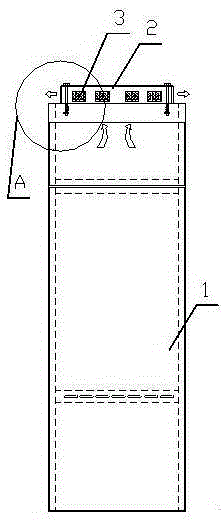
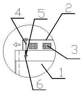
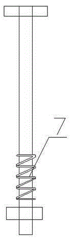
[0012] Such as Figure 1 to Figure 4 As shown, an electrical switchgear pressure relief device, the electrical switchgear pressure relief device includes a pressure relief cover 2 arranged on the top of the switch cabinet 1, the four corners of the pressure relief cover 2 are connected to the top of the switch cabinet 1 by bolts 4 Edge connection, the lower end of the bolt 4 is set with a compression spring 5 and finally fixed with the nut 6, so that there is a certain distance between the nut 6 and the top of the switch cabinet 1; the pressure relief cover 2 is also provided with a pressure relief hole 3 , A rotating bar 7 is also provided at the bottom of the bolt, and a rotating groove matched with the rotating bar is provided in the through hole for the bolt to pass through on the top edge of the switch cabinet.

[0013] The length of the ...


PUM


Abstract

The invention discloses a voltage release device of an electrical switch cabinet. The voltage release device is characterized by comprising a voltage release hood arranged at the top of the switch cabinet, wherein four corners of the voltage release hood are connected with the edge of the top of the switch cabinet through bolts; a compression spring sleeves the lower end of each bolt, and is finally fixed by nuts, so that a certain distance is retained between the nuts and the top of the switch cabinet; voltage release holes are also formed in the periphery of the voltage release hood; rotating strips are further arranged at the lower parts of the bolts; and rotating grooves matched with the rotating strips are formed in through holes where the bolts at the edge of the top of the switch cabinet pass. The voltage release device is simple in structure and convenient to use; when equipment works normally, the voltage release holes in the periphery of the voltage release hood can help the interior of the switch cabinet to be ventilated and dissipated, so that the probability of internal fault occurring is reduced.

Description

technical field [0001] The invention relates to a pressure relief device for an electric switch cabinet. Background technique [0002] The switchgear is a large electrical equipment with a large number of electronic components inside, which will generate a lot of heat during operation; during normal operation, the heat will be dissipated through the cooling holes on the switchgear body. However, once the internal components of the switchgear fail, a large amount of heat and pressure will be generated, and the heat dissipation holes on the switchgear body cannot quickly release the energy inside the switchgear body, which may cause the danger of the switchgear explosion, bringing Huge security risks and economic losses. Contents of the invention [0003] The object of the present invention is to provide a pressure relief device for an electrical switchgear. [0004] In order to achieve the above object, the following technical solution is adopted, an electrical switch c...

Claims


Application Information

Patent Timeline
Patent Type & Authority Applications(China)
IPC IPC(8): H02B1/30H02B1/56
CPCH02B1/306H02B1/565
Inventor 周祥桥唐均德
Owner CHONGQING XINDASHUN ELECTRICAL APPLIANCE CO LTD
Why Eureka
Try Eureka