
Piston assembly for novel engine and novel engine

A technology for piston assemblies and engines, which is applied in engine components, engine lubrication, engine control, etc., and can solve problems such as power loss, inability to achieve energy saving, and poor emissions.

Pending Publication Date: 2020-07-07
王芳华
View PDF0 Cites 2 Cited by
  • Summary
  • Abstract
  • Description
  • Claims
  • Application Information

AI Technical Summary

Problems solved by technology

[0004] However, this single-cylinder engine has the following problems: (1) Both ends of the piston do work through gasoline combustion, so it is impossible to achieve oil injection lubrication, and it can only be lubricated by mixing engine oil in gasoline, resulting in high cost of use, and the oil burns when it is discharged. Poor discharge; (2) The piston ring needs to pass through the intake valve, which increases the friction and causes the piston ring to be undurable; (3) Since the combustion chambers on both sides of the piston share an intake valve, when the gas on the other side is compressed, it opens The intake valve causes the loss of high pressure in the cylinder itself, resulting in power loss; (4) The intake valve of the Israeli engine cannot be controlled by time, cannot use Atkinson technology, and cannot achieve energy saving

Method used


Image

  • Piston assembly for novel engine and novel engine
  • Piston assembly for novel engine and novel engine
  • Piston assembly for novel engine and novel engine

Examples


Embodiment Construction

[0024] The specific implementation manner of the present invention will be described in detail below in conjunction with the accompanying drawings.

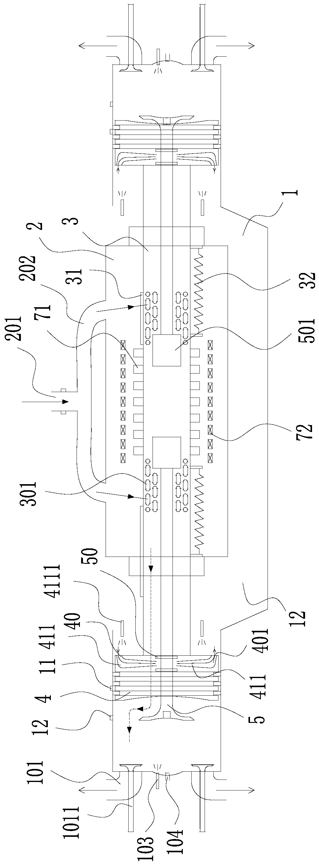
[0025] Such as figure 1Shown, a kind of novel engine, the main shaft of this engine is supported by two linear bearings, and this engine comprises outer casing 1, sealed compartment cylinder body 2, piston connecting pipe 3 and the piston assembly at both ends thereof, and piston assembly comprises piston 4 and can The air door 5 is changed, the airtight cabin cylinder body 2 is located in the middle of the outer shell body 1, the upper part of the airtight cabin cylinder body 2 is provided with an air intake main duct 201, and an air flow meter is arranged on the air intake main duct 201 to facilitate better control of the air intake air. The bottom of the intake main pipe 201 is connected to two intake branch pipes 202, and the two intake branch pipes 202 lead to the left and right sides respectively, and the compressor presse...


PUM


Abstract

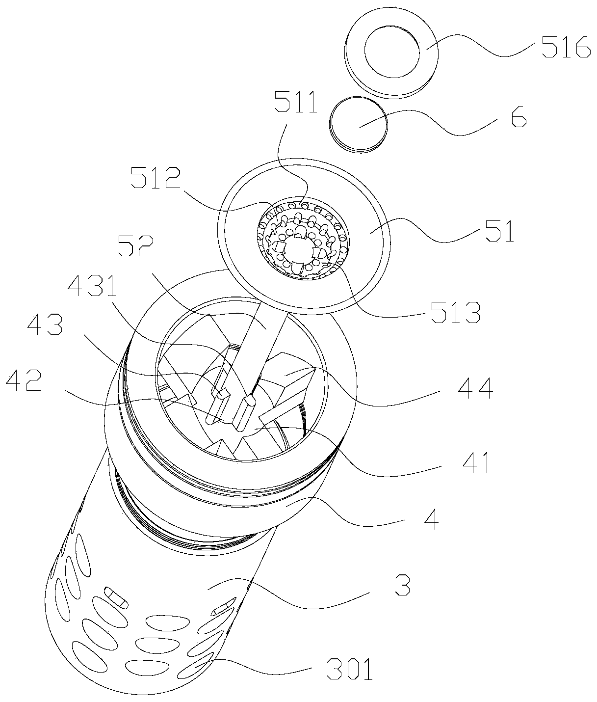
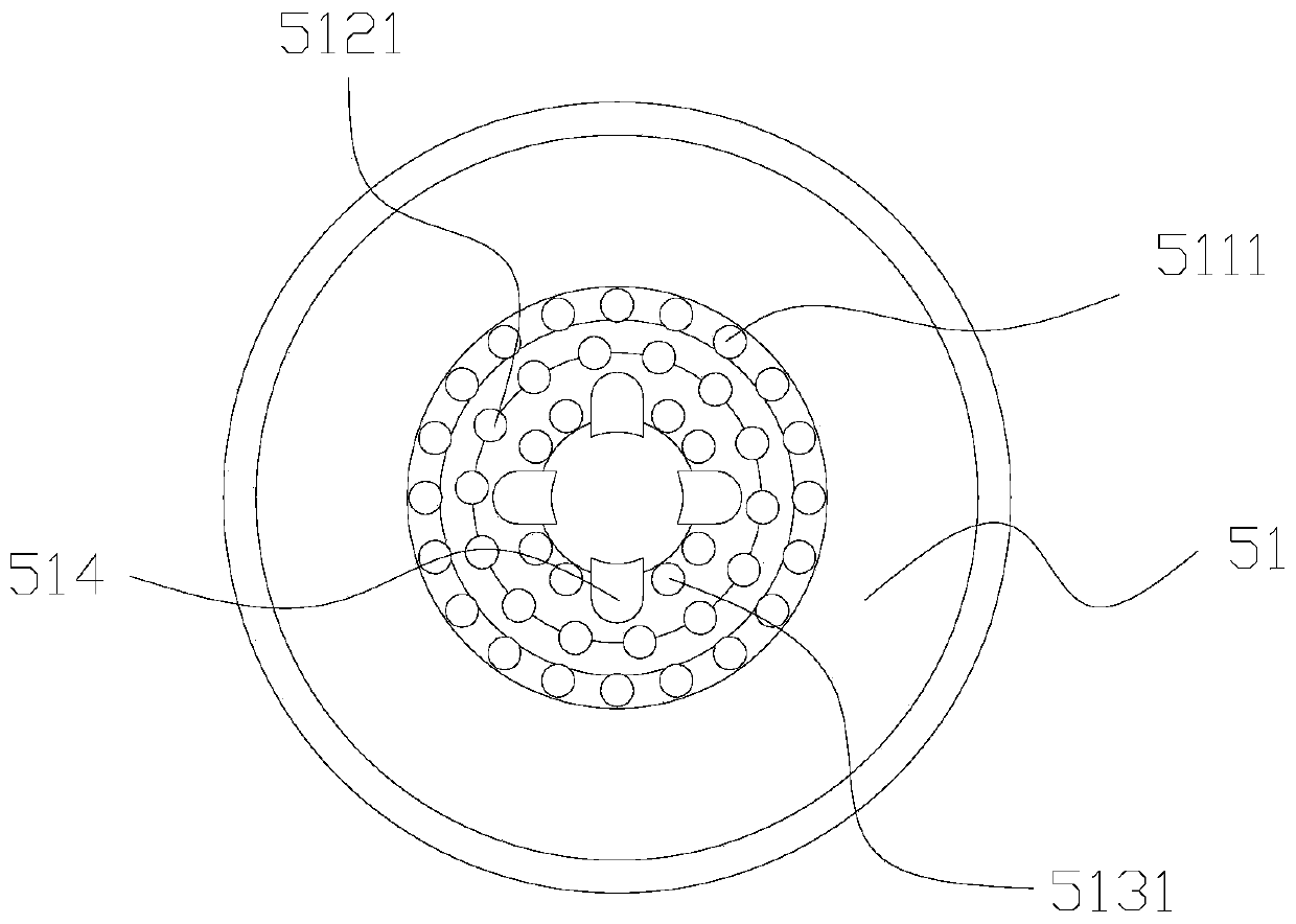
The invention relates to the technical field of engines, in particular to a piston assembly for a novel engine and the novel engine. The piston assembly comprises a piston and a variable hollow air valve, wherein a cross-shaped supporting frame is arranged in the middle of the piston, an air valve through hole is formed in the middle of the cross-shaped supporting frame, a plurality of matching lugs are arranged on the cross-shaped supporting frame, a valve seat is arranged at the position, between the piston and the end matching with the variable hollow air valve, of the piston, the variablehollow air valve comprises a hollow air valve body and a valve rod, a first annular groove is formed in the middle of the hollow air valve body and provided with a plurality of first deflation throughholes, a second annular groove is formed in the middle of the first annular groove, a plurality of matching through holes are formed in the second annular groove, the plurality of matching lugs penetrate through the plurality of matching through holes and are provided with a circle center valve seat, and a hollow plugging circular ring is further arranged on the first annular groove. The piston assembly for the novel engine and the novel engine have the advantages that exhaust is cleaner, mechanical friction is reduced, an intake valve is controlled in time, the compression ratio is variable,the heat efficiency and power are improved, and a two-stroke linear internal combustion engine exhaust Atkinson technology is used.

Description

technical field [0001] The invention relates to the technical field of engines, in particular to a piston assembly for a novel engine and a novel engine. Background technique [0002] Engine A machine that can convert other forms of energy into mechanical energy, including internal combustion engines, external combustion engines, electric motors, etc. For example, internal combustion engines usually convert chemical energy into mechanical energy. The engine is not only applicable to the power generating device, but also refers to the whole machine including the power device. [0003] At present, most of the car engines on the market are four-stroke engines, and there is a new type of Israeli engine, which is a two-stroke engine. The principle is that a piston moves back and forth in the cylinder to make the internal gas compress and ignite. In this way, the chemical energy is converted into mechanical energy through back and forth compression ignition, the piston drives th...

Claims


Application Information

Patent Timeline
IPC IPC(8): F02F3/00F01L11/02F01L3/20F01L3/22F01L9/04F01M1/08F01M9/10F02B75/26F02B63/04F02F1/22F02F7/00F01L1/26F02M35/10F02B33/02F02B39/10F02D13/02F02D41/00F02D41/06F01L9/21
CPCF02F3/00F01L11/02F01L3/20F01L3/22F01M1/08F01M9/103F02B75/26F02B63/041F02F1/22F02F7/0021F01L1/265F02M35/10091F02M35/1015F02B33/02F02B39/10F02D13/0253F02D13/0257F02D13/0223F02D13/0242F02D41/0007F02D41/062F02B2075/1808F02D2041/001F01L2009/2103F01L9/20Y02T10/12
Inventor 王芳华
Owner 王芳华
Learn More