Electric rotating machine
A technology of rotating motors and rotating axes, which is applied in electromechanical devices, electrical components, wind power generation, etc., and can solve problems such as increased cogging torque, increased vibration, and noise
- Summary
- Abstract
- Description
- Claims
- Application Information
AI Technical Summary
Problems solved by technology
Method used
Image

Examples
no. 1 example
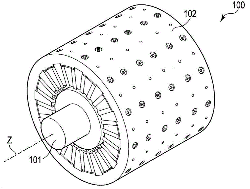
[0046] figure 1 The rotating electric machine 100 according to the first embodiment is schematically shown. Such as figure 1As shown, the rotating electrical machine 100 includes a rotor 101 supported by a bearing (not shown) so as to be rotatable around a rotation axis z, and a stator 102 opposed to the outer peripheral surface of the rotor 101 with a predetermined gap between them. gap. The rotor 101 has an approximately cylindrical shape surrounding the axis of rotation z. The stator 102 has an approximately cylindrical shape coaxial with the rotation axis z, and is arranged to cover the rotor 101 around the rotation axis z. The rotor 101 is positioned inside the stator 102 .
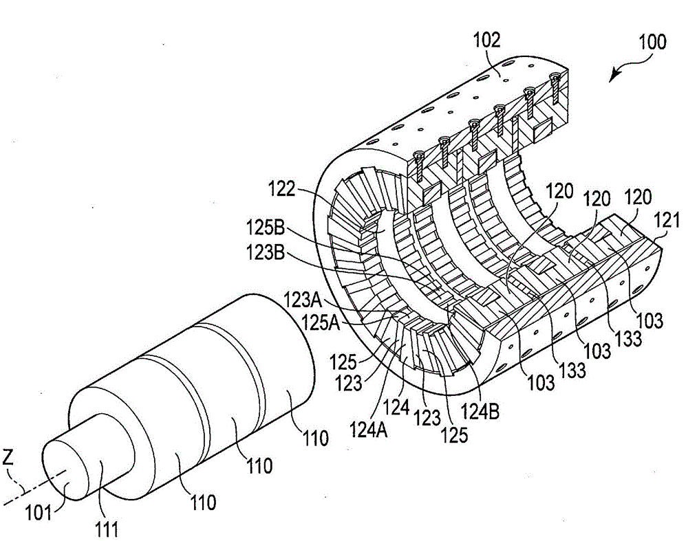
[0047] figure 2 The rotary electric machine 100 is schematically shown in a state disassembled into a rotor 101 and a stator 102 with the stator 102 partially cut away. Such as figure 2 As shown, the rotating electric machine 100 is a three-stage (three-phase) type rotating electric machine ...
no. 2 example
[0067] In the second embodiment, explanation of the same components as those of the first embodiment will be omitted as necessary, and the explanation will focus on those components that are different from the first embodiment.
[0068] Figure 6 A rotating electrical machine 200 according to the second embodiment is schematically shown. Such as Figure 6 As shown, the rotary electric machine 200 includes a rotor 101 supported by a bearing (not shown) so as to be rotatable about a rotation axis z, and a stator 202 disposed opposite to an outer peripheral surface of the rotor 101 with a predetermined gap therebetween. The stator 202 has an approximately cylindrical shape coaxial with the axis of rotation z. The rotor 101 is positioned inside the stator 202 .
[0069] Figure 7 The rotating electrical machine 200 is schematically shown in a state of being disassembled into a rotor 101 and a stator 202 . Such as Figure 7 As shown, the rotating electrical machine 200 is a t...
no. 3 example
[0079] In the third embodiment, explanation of the same components as those of the first embodiment will be omitted as necessary, and the explanation will focus on those components that are different from the first embodiment.
[0080] Figure 11 A rotating electrical machine 300 according to the third embodiment is schematically shown. Such as Figure 11 As shown, the rotary electric machine 300 includes a rotor 101 supported by a bearing (not shown) so as to be rotatable about a rotation axis z, and a stator 302 disposed opposite to an outer peripheral surface of the rotor 101 with a predetermined gap therebetween. The stator 302 has an approximately cylindrical shape and is arranged coaxially with the axis of rotation z. The rotor 101 is positioned inside the stator 302 .
[0081] Figure 12 The rotary electric machine 300 is schematically shown in a state of being disassembled into a rotor 101 and a stator 302 . Such as Figure 12 As shown, the rotating electrical ma...
PUM
 Abstract
Description
Claims
Application Information
 - R&D
- Intellectual Property
- Life Sciences
- Materials
- Tech Scout
- Unparalleled Data Quality
- Higher Quality Content
- 60% Fewer Hallucinations
Browse by: Latest US Patents, China's latest patents, Technical Efficacy Thesaurus, Application Domain, Technology Topic, Popular Technical Reports.
© 2025 PatSnap. All rights reserved.Legal|Privacy policy|Modern Slavery Act Transparency Statement|Sitemap|About US| Contact US: help@patsnap.com