Supercharge Your Innovation With Domain-Expert AI Agents!

High rejection surface acoustic wave filter

A surface acoustic wave and acoustic wave technology, applied in the direction of impedance network, electrical components, etc., can solve problems that have not been considered, and achieve the effects of reducing acoustic wave coupling, increasing suppression, and improving isolation effect

Inactive Publication Date: 2016-02-10
雷森南特责任有限公司
View PDF4 Cites 0 Cited by
  • Summary
  • Abstract
  • Description
  • Claims
  • Application Information

AI Technical Summary

Problems solved by technology

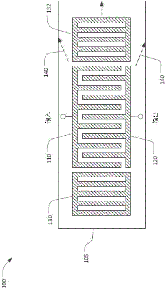
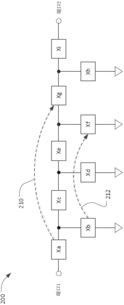
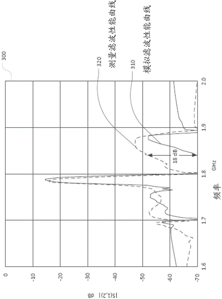
For practical filters, the unexpectedly low insertion loss occurring in the above frequency bands is at least partly due to the existence of acoustic leakage paths, which were not considered in the electromagnetic simulations

Method used


Image

  • High rejection surface acoustic wave filter
  • High rejection surface acoustic wave filter
  • High rejection surface acoustic wave filter

Examples


Embodiment Construction

[0043] Figure 4 is an enlarged schematic view of a duplexer 400 fabricated by depositing a thin-film conductor on a piezoelectric substrate 410 . Each of the block-shaped areas marked X1 to X23 represents a SAW resonator, as shown, a SAW resonator is formed by a plurality of extremely small crossing conductors. The frequencies of resonance and anti-resonance are primarily determined by the spacing and orientation of the cross conductors, the choice of substrate material, and the crystal orientation of the substrate material. As known in the prior art, each of the SAW resonators X1 to X23 exhibits a resonant property in a first frequency state and an anti-resonant property in a second frequency state.

[0044] The above-mentioned 23 SAW resonators are connected to each other through thin film conductors, thereby forming a duplexer circuit. The duplexer 400 includes an input board, an antenna board and an output board (labeled "in", "ant" and "out" respectively) for connectin...


PUM


Abstract

A filter includes two or more surface acoustic wave resonators formed on a surface of a substrate and at least one ground conductor formed on the surface of the substrate. At least a portion of an edge of the ground conductor is formed as a plurality of serrations.

Description

[0001] Copyright and Trade Dress Notice: [0002] Portions contained in this patent document are protected by copyright. This patent document may show and / or describe the trade dress that belongs or will belong to the right holder. The copyright and trade dress owners have no objection to the facsimile reproduction by anyone of the patent disclosure as disclosed in the Patent and Trademark Office patent file or records. Otherwise, in all cases, the right holder reserves all copyright and trade dress rights. [0003] This patent application claims priority to U.S. Provisional Patent Application, Publication No. 62 / 029,279, filed July 25, 2014, entitled "High Isolation Duplexer," the entire contents of which are hereby incorporated herein by reference. Applying. technical field [0004] The present application relates to a radio frequency filter using a surface acoustic wave (SAW) resonator, and more particularly to a filter and a duplexer including the SAW resonator to provi...

Claims


Application Information

Patent Timeline
Patent Type & Authority Applications(China)
IPC IPC(8): H03H9/64
CPCH03H9/02818H03H9/02905H03H9/02992H03H9/6409H03H9/6483H03H9/725
Inventor J·R·哥斯达K·赖恩
Owner 雷森南特责任有限公司
Features
  • R&D
  • Intellectual Property
  • Life Sciences
  • Materials
  • Tech Scout
  • Unparalleled Data Quality
  • Higher Quality Content
  • 60% Fewer Hallucinations
Learn More