Heat radiation device of display device

A technology of heat sink and display, applied in cooling/ventilation/heating transformation, etc., can solve the problem of high image source temperature, and achieve the effect of reducing image source temperature and contact thermal resistance

Active Publication Date: 2016-02-10
LUOYANG INST OF ELECTRO OPTICAL EQUIP OF AVIC
View PDF7 Cites 3 Cited by
  • Summary
  • Abstract
  • Description
  • Claims
  • Application Information

AI Technical Summary

Problems solved by technology

[0004] The purpose of the present invention is to provide a heat dissipation device for a display to solve

Method used


Image

  • Heat radiation device of display device

Examples


Embodiment Construction

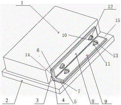
[0017] The embodiment of the cooling device of the display in the present invention is such as figure 1 Shown: the display includes an image source and a display casing 2 . The image source includes an image source housing 1 . After the image source casing 1 is adjusted to the set position by the position adjustment washer, it is installed on the mounting surface of the display casing 2 with screws. At least one side of the image source housing 1 is an image source housing heat dissipation plane 14, and the display housing 2 is provided with a display housing heat dissipation plane 15 corresponding to the image source housing heat dissipation plane 14, and the display also includes a radiator 5, The radiator 5 includes a first heat dissipation plate 6 connected in parallel to the heat dissipation plane 14 of the image source housing and a second heat dissipation plate 7 connected in parallel to the heat dissipation plane 15 of the display housing. The first heat dissipation p...


PUM


Abstract

The invention relates to a heat radiation device of a display device. The heat radiation device of the display device comprises an image source shell and a display device shell, wherein at least one side surface of the image source shell is an image source shell heat radiation plane, the display device shell is provided with a display device shell heat radiation plane corresponding to the image source shell heat radiation plane, and the heat radiation device of the display device also comprises a heat radiator, the heat radiator comprises a first heat radiation plate which is connected with the image source shell heat radiation plane in parallel in a heat conduction manner and a second heat radiation plate which is connected with the display device shell heat radiation plane in parallel in a heat conduction manner, and the first heat radiation plate and the second heat radiation plate are respectively of an integral structure. The image source shell heat radiation plane and the display device shell heat radiation plane are connected in parallel in a heat conduction manner by virtue of the heat radiator, so that the contact heat resistance of the image source shell and the display device shell is reduced, the heat of the image source shell can be transferred to the display device shell, and the temperature of an image source is further decreased.

Description

technical field [0001] The invention relates to the technical field of heat dissipation of a display, in particular to a heat dissipation device of a display. Background technique [0002] The image source is an important component of the display. In order to increase the brightness of the image source, it is usually realized through circuit adjustment, which will cause the power of the image source to increase, so that the image source will generate more heat and the temperature will be too high, and then thermal protection will occur, affecting the normal operation of the display. Work. This problem is more obvious in digital image sources, which have the disadvantage of low brightness. Generally, in order to increase the brightness of the digital image source, it is necessary to increase the circuit adjustment. [0003] At present, the heat dissipation of the image source of the display is carried out through natural heat dissipation. The image source is in a closed s...

Claims


Application Information

Patent Timeline
IPC IPC(8): H05K7/20
Inventor 张小军
Owner LUOYANG INST OF ELECTRO OPTICAL EQUIP OF AVIC
Why Eureka
Try Eureka