Scaffold steel pipe carrying device

A handling device and scaffolding technology, which is applied in the direction of transportation and packaging, trolleys, multi-axis trolleys, etc., can solve problems such as high labor intensity, increased workload, and personnel injuries, so as to improve transportation efficiency, improve work efficiency, and prevent bases The effect of moving

Active Publication Date: 2016-02-17
STATE GRID SHANDONG JIYANG POWER SUPPLY +1
View PDF5 Cites 12 Cited by
  • Summary
  • Abstract
  • Description
  • Claims
  • Application Information

AI Technical Summary

Problems solved by technology

[0002] The steel pipes of the existing scaffolding are basically stacked in a conical shape. This method occupies a large storage area and has low site utilization efficiency. If the stacking is too high, it will easily cause the upper cement pole to slip, causing damage to the cement pole and personnel injury. To solve this problem , the existing method basically adopts the reinforcement of cement rods on both sides of the bottom layer, and places triangle or wedge-shaped fixing devices (stones, steel, etc.) under the cement rods on both sides of the bottom layer for reinforcement.
Access to the bottom cement rod can only be performed after removing the upper cement rod, resulting in increased workload
Especially in the handling process, it needs to be transported and loaded one by one, the labor intensity is very high, and the risk factor is high during the handling process.

Method used


Image

  • Scaffold steel pipe carrying device
  • Scaffold steel pipe carrying device
  • Scaffold steel pipe carrying device

Examples


Embodiment Construction

[0028] A scaffold steel pipe handling device of the present invention will be described in detail below with reference to the accompanying drawings.

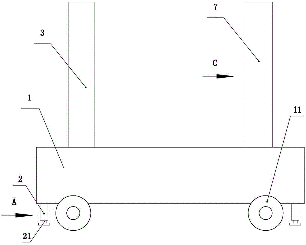
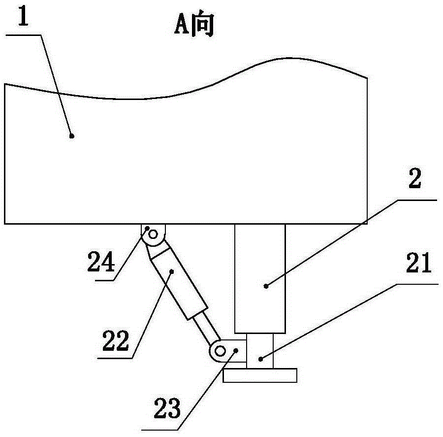
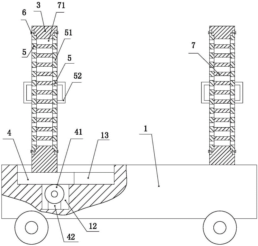
[0029] As shown in the figure, a steel pipe handling device for scaffolding of the present invention has a structure including a base 1, a movable support 3 and a fixed support 7, the fixed support 7 is fixedly connected to the base 1, and the movable support 3 is slidably connected to the base 1 ;

[0030] Described base 1 is provided with chute 13, and the bottom of described movable support 3 is connected with rack 4, and described rack 4 is arranged in chute 13, and the bottom of chute 13 is provided with a groove 12, and described groove The groove 12 is provided with a gear 41 and a motor 42, the rack 4 is connected with the gear 41, the gear 41 is connected with the motor 42, and the motor 42 is connected with the controller; the motor 42 drives the gear 41 to rotate, and the rotation of the gear 41 drives the gear The m...


PUM


Abstract

The invention discloses a scaffold steel pipe carrying device. The structure of the device comprises a base, a moveable support, and a fixed support. The fixed support is fixedly connected with the base. The moveable support is slidably connected with the base. The base is provided with a sliding chute. The bottom of the moveable support is connected with a rack. The rack is arranged in the sliding chute. The lower part of the sliding chute is provided with a groove. The groove is internally provided with a gear and a motor. The rack and the gear are connected in a cooperated manner. The gear is connected with the motor. The motor is connected with a controller. The carrying device provides convenience for centralized storage and carrying of steel pipes. Width of the support can be adjusted at will according to differences of the steel pipes, so that the device is suitable for carrying steel pipes in different diameters and lengths. The device saves time and efforts, greatly reduces labor intensity, and improves carrying efficiency.

Description

technical field [0001] The invention relates to a conveying device, in particular to a scaffold steel pipe conveying device. Background technique [0002] The steel pipes of the existing scaffolding are basically stacked in a conical shape. This method occupies a large storage area and has low site utilization efficiency. If the stacking is too high, it will easily cause the upper cement pole to slip, causing damage to the cement pole and personnel injury. To solve this problem , the existing mode basically adopts the cement rods on both sides of the reinforcement bottom, and pads triangle or wedge-shaped fixtures (stones, steel, etc.) under the cement rods on both sides of the bottom to reinforce. Access to the bottom cement rod can only be performed after the upper cement rod is removed, resulting in increased workload. Especially in the handling process, it is necessary to carry and load the roots one by one, the labor intensity is very large, and the risk factor is high...

Claims


Application Information

Patent Timeline
Patent Type & Authority Applications(China)
IPC IPC(8): B62B3/02B62B3/10
CPCB62B3/02B62B3/102
Inventor 张明王秋香鹿静徐玉姣杨岱芬窦胜男李文静
Owner STATE GRID SHANDONG JIYANG POWER SUPPLY
Why Eureka
Try Eureka