
Landing platform for flight device

A technology for landing platforms and flying devices, applied in landing gear, aircraft parts, transportation and packaging, etc., can solve problems such as difficulty in maintaining the level of the flying device

Inactive Publication Date: 2016-02-17
ANHUI UNIVERSITY
View PDF5 Cites 10 Cited by
  • Summary
  • Abstract
  • Description
  • Claims
  • Application Information

AI Technical Summary

Problems solved by technology

[0004] The invention provides a landing platform for flying devices, which solves the problem in the prior art that it is difficult for flying devices to maintain a level due to landing on rough roads. The specific technical solutions are as follows:

Method used


Image

  • Landing platform for flight device
  • Landing platform for flight device

Examples


Embodiment 1

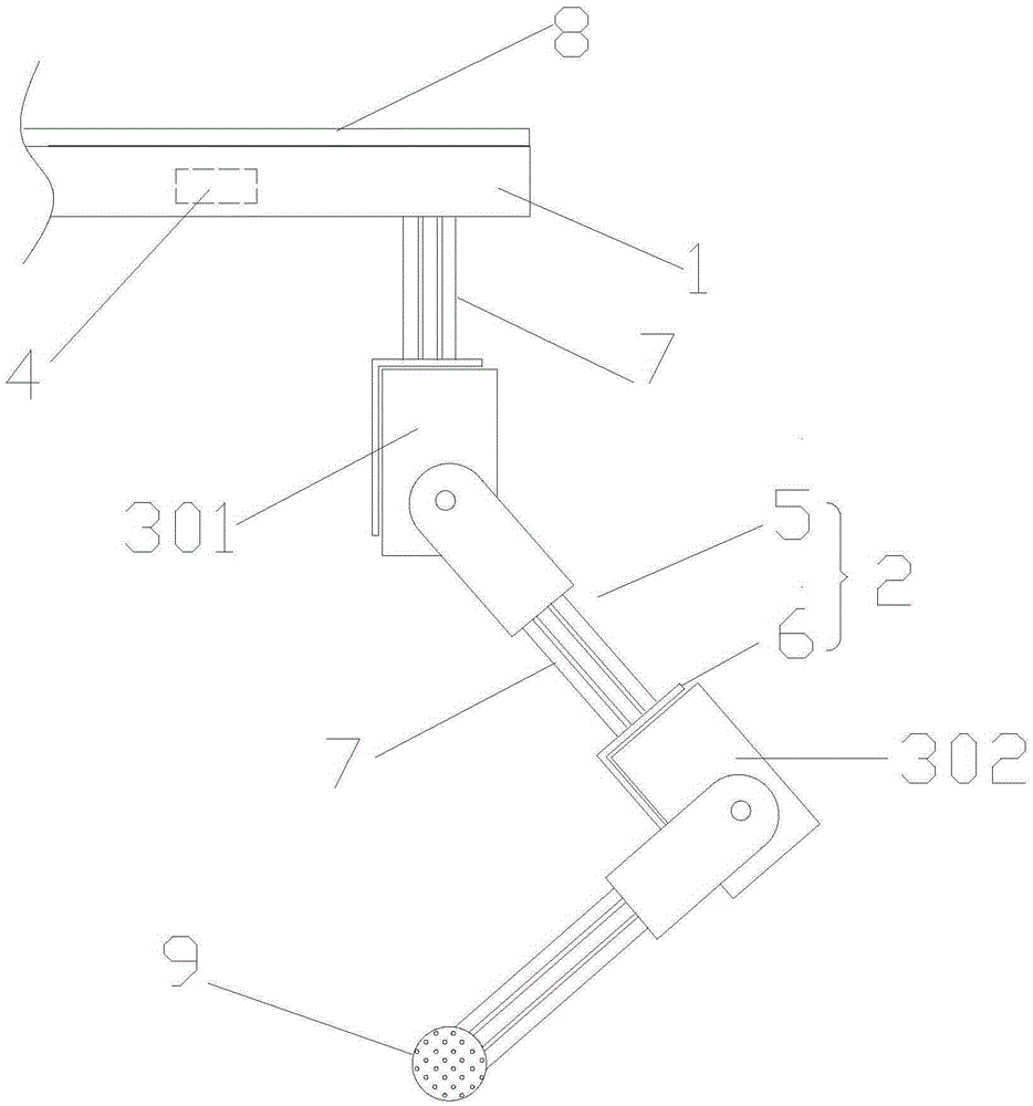
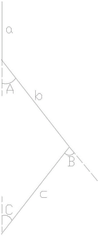
[0017] figure 1 It is a structural schematic diagram of a landing platform, which is a landing platform for flying devices, including: a frame 1 and a support foot 2 arranged at the bottom of the frame 1, the number of the support feet 2 is 4, and the landing platform also includes a gyroscope 3 , sensor 4 and controller, sensor 4 adopts 6050 three-axis acceleration gyroscopes in the present embodiment, controller adopts stm32 single-chip microcomputer, each supporting foot 2 includes connecting part 5 and joint support 6, and the fuselage of gyroscope 3 is fixed on the joint On the bracket 6, the rotating output end of the gyro machine 3 is fixedly connected with the connecting part 5, and the gyro machine 3 drives the connecting part 5 to rotate on the joint support 6, and the connecting part 5, the gyro machine 3 and the joint support 6 form a joint with a degree of freedom. The supporting foot 2 has two degrees of freedom joints distributed up and down. The two degrees of ...


PUM


Abstract

The invention relates to a landing device, in particular to a landing platform for a flight device. The landing platform comprises a frame and three or more supporting legs arranged at the bottom of the frame. The landing platform further comprises steering engines, a sensor and a controller. The sensor detects the tilting direction and tilting angle of the landing platform, receives signals of the sensor and controls different steering engines to conduct transmission at corresponding angles. Rotation of the steering engines causes bending of the supporting legs so as to control the corresponding adjustment height of the supporting legs in the vertical direction and keep the landing platform horizontal in real time. By the application of the landing platform for the flight device, the landing range of a rotor craft such as a four-axel aircraft applied quite widely currently can be greatly expanded; the landing platform can be applied to such fields as aerial photography, plant protection and engineering surveying.

Description

technical field [0001] The invention relates to a landing device, in particular to a landing platform for a flying device. Background technique [0002] Four-axis aircraft, referred to as four-axis, four-rotor, is a multi-rotor aircraft. The four propellers of the four-axis aircraft are simple mechanisms directly connected to the motor. The cross-shaped layout allows the aircraft to obtain the force of rotating the fuselage by changing the speed of the motor. , so as to adjust its own attitude. Thanks to the development of micro-electromechanical control technology in recent years, stable quadcopters have received extensive attention, and their application prospects are very promising. [0003] Quadcopters in the prior art have a wide range of applications, so they have to deal with various harsh landing environments, while the landing devices of most aircraft are only suitable for relatively flat ground, especially for shooting or where the level of the aircraft is high. T...

Claims


Application Information

Patent Timeline
Patent Type & Authority Applications(China)
IPC IPC(8): B64C25/08B64C25/32
CPCB64C25/08B64C25/32
Inventor 蒋涛王竞成刘昆
Owner ANHUI UNIVERSITY
Learn More