
Steel angle plate-type anchoring connection joint for buckling-restrained brace and concrete beam column

A technology of concrete beams and buckling constraints, which is applied in the directions of building components, earthquake resistance, construction, etc., can solve problems affecting concrete pouring and steel bar construction, affecting layout, and the reduction of concrete co-working ability of concrete beam-column joints, etc., to achieve enhanced co-working Ability, guaranteed stability, effect of guaranteed stress stability

Inactive Publication Date: 2016-02-17
SHENYANG JIANZHU UNIVERSITY
View PDF5 Cites 0 Cited by
  • Summary
  • Abstract
  • Description
  • Claims
  • Application Information

AI Technical Summary

Problems solved by technology

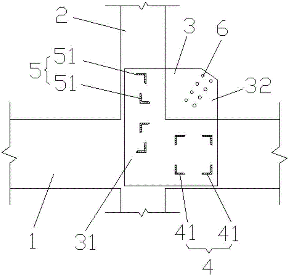
[0004] The above-mentioned structure using H-shaped steel anchored in concrete beams and columns can enhance the strength of beams and columns to a certain extent, and can restrain the plastic deformation of beams and columns to a certain extent, but the contact area of ​​H-shaped steels in concrete is large, which will make concrete beams and columns The joints are divided into more areas according to the number of H-shaped steels, which leads to the reduction of the concrete cooperating ability of the concrete beam-column joints, and the concrete at the contact point with the H-shaped steels has obvious stress concentration, and the H-shaped steels occupy a large area in the concrete beam-column , it is likely to affect the layout of the stirrups and longitudinal bars in the original concrete beams and columns, and then affect the concrete pouring and steel bar construction
Moreover, there are fewer types of H-shaped steel, so it cannot be used for some structures. It can only adopt the lattice structure, that is, it is welded by three steel plates. There are many processing procedures and complicated operations.

Method used


Image

  • Steel angle plate-type anchoring connection joint for buckling-restrained brace and concrete beam column
  • Steel angle plate-type anchoring connection joint for buckling-restrained brace and concrete beam column
  • Steel angle plate-type anchoring connection joint for buckling-restrained brace and concrete beam column

Examples


Embodiment Construction

[0021] The following will clearly and completely describe the technical solutions in the embodiments of the present invention with reference to the accompanying drawings in the embodiments of the present invention. Obviously, the described embodiments are only part of the embodiments of the present invention, not all of them. Based on the embodiments of the present invention, all other embodiments obtained by persons of ordinary skill in the art without creative efforts fall within the protection scope of the present invention.

[0022] It should be noted that all directional indications (such as up, down, left, right, front, back...) in the embodiments of the present invention are only used to explain the relationship between the components in a certain posture (as shown in the accompanying drawings). Relative positional relationship, movement conditions, etc., if the specific posture changes, the directional indication will also change accordingly.

[0023] In addition, the ...


PUM


Abstract

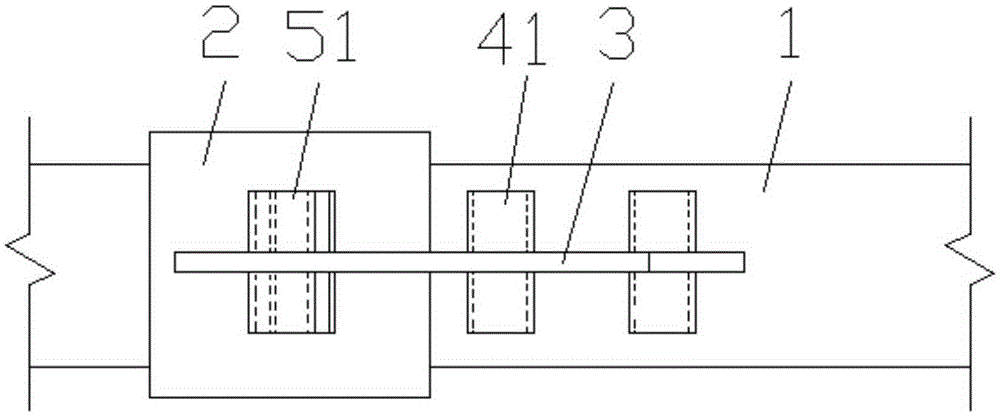
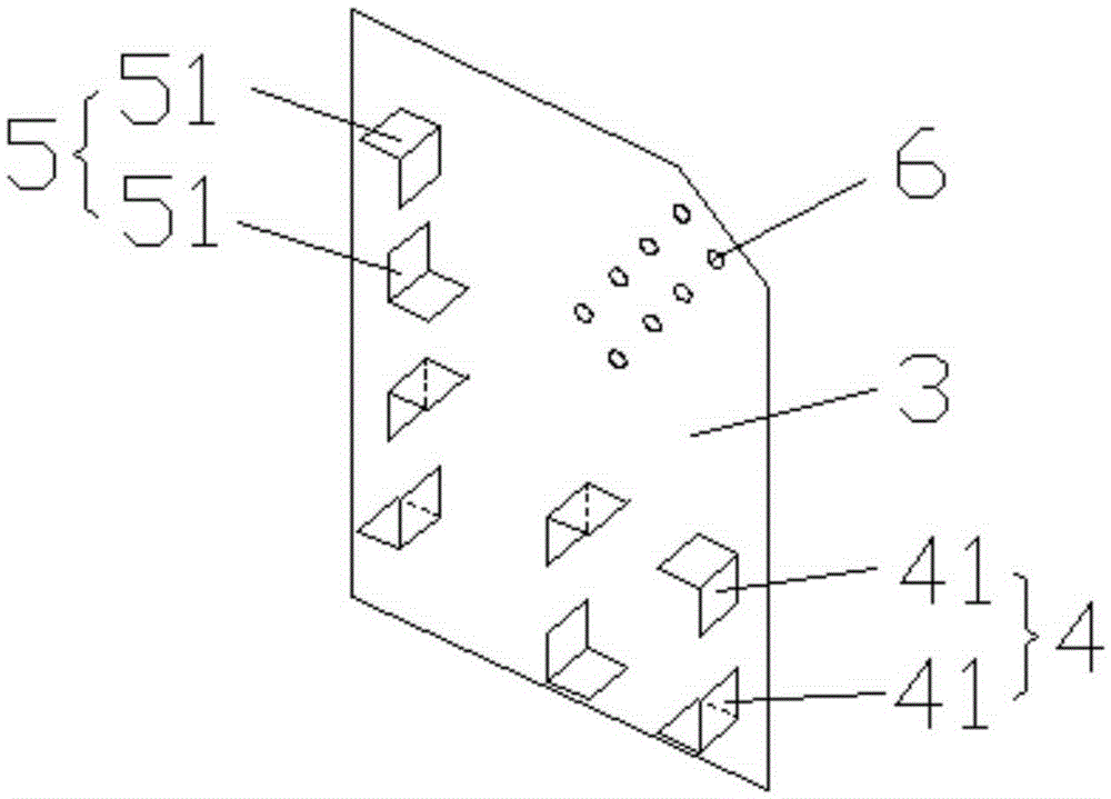
The invention discloses a steel angle plate-type anchoring connection joint for a buckling-restrained brace and a concrete beam column. The steel angle plate-type anchoring connection joint comprises a joint plate which is anchored to the joint position of a concrete beam and a concrete column. The joint plate is provided with a first part which is anchored into the concrete beam and the concrete column, and a second part which is located outside the concrete beam and the concrete column. A plurality of steel angle sets are symmetrically welded to the front surface and the back surface of the first part, and the steel angle sets comprise the first steel angle set located inside the concrete beam and the second steel angle set located inside the concrete column. The first steel angle set is provided with four first steel angles to be surrounded, and the adjacent first steel angles are arranged in an axial symmetry mode. The second steel angle set is provided with two second steel angles to be arrayed in a row, and the two second steel angles are arranged in a central symmetry mode. The second part is provided with threaded holes allowing the buckling-restrained brace to be fixedly connected. By the adoption of the arraying mode of the steel angles, the joint plate can transfer force to the concrete beam column evenly, the stress stability of the joint plate is guaranteed, and the anti-seismic property of joints is improved.

Description

technical field [0001] The invention relates to a building structure, in particular to a buckling-constrained support and a concrete beam-column angle steel plate type anchor connection node. Background technique [0002] Concrete frame structures with buckling-restrained braces are being popularized and applied in the field of construction due to their superior properties such as seismic performance, simple construction, and saving raw materials. Among them, the connection node between the buckling restraint support and the concrete frame is a very important link in the whole structure. It needs to have sufficient strength, appropriate stiffness, and sufficient rotation capacity to transmit shear force and bending moment reasonably, and at the same time, it must be easy It is easy to make and construct, and good joints should conform to the design principle of "strong joints, weak components". [0003] In order to meet the above requirements, technicians have done research...

Claims


Application Information

Patent Timeline
Patent Type & Authority Applications(China)
IPC IPC(8): E04B1/58E04B1/98
CPCE04B1/58E04B1/98E04B2001/5875
Inventor 李帼昌李文明杨志坚
Owner SHENYANG JIANZHU UNIVERSITY
Learn More