Precast concrete column and steel beam connecting joint with inner partition plates

A technology of prefabricated concrete and connecting nodes, which is applied in the direction of architecture and building construction, can solve the problems of pressure damage in the node area, difficult positioning of steel beams, and complicated structural schemes, so as to ensure construction quality, improve collaborative work performance, and save energy. The effect of the amount of steel used

Pending Publication Date: 2020-04-17
TIANJIN UNIV RES INST OF ARCHITECTRUAL DESIGN & URBAN PLANNING
View PDF0 Cites 2 Cited by
  • Summary
  • Abstract
  • Description
  • Claims
  • Application Information

AI Technical Summary

Problems solved by technology

[0003] The mixed frame structure of reinforced concrete columns and steel beams can give full play to the advantages of concrete columns and steel beams, and is a low-cost and high-efficiency structural form. The penetration of steel beams will cause pressure damage in the joint area, which needs to be avoided by complex structural measures. If the joint area adopts the traditional column-through reinforced concrete-steel beam connection structure, in order to ensure the bearing capacity and energy dissipation capacity of the joint area, The amount of steel used in the joint area will be greatly increased, and problems such as difficult positioning of steel beams and complex structural schemes are still difficult to solve

Method used


Image

  • Precast concrete column and steel beam connecting joint with inner partition plates
  • Precast concrete column and steel beam connecting joint with inner partition plates
  • Precast concrete column and steel beam connecting joint with inner partition plates

Examples


Embodiment Construction

[0027] In order to further understand the invention content, characteristics and effects of the present invention, the following examples are given, and detailed descriptions are as follows in conjunction with the accompanying drawings:

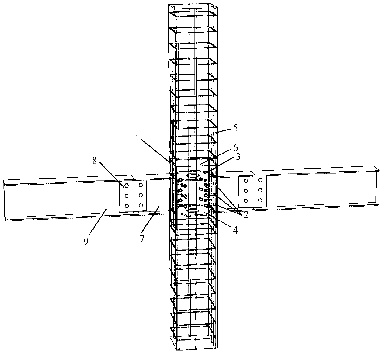
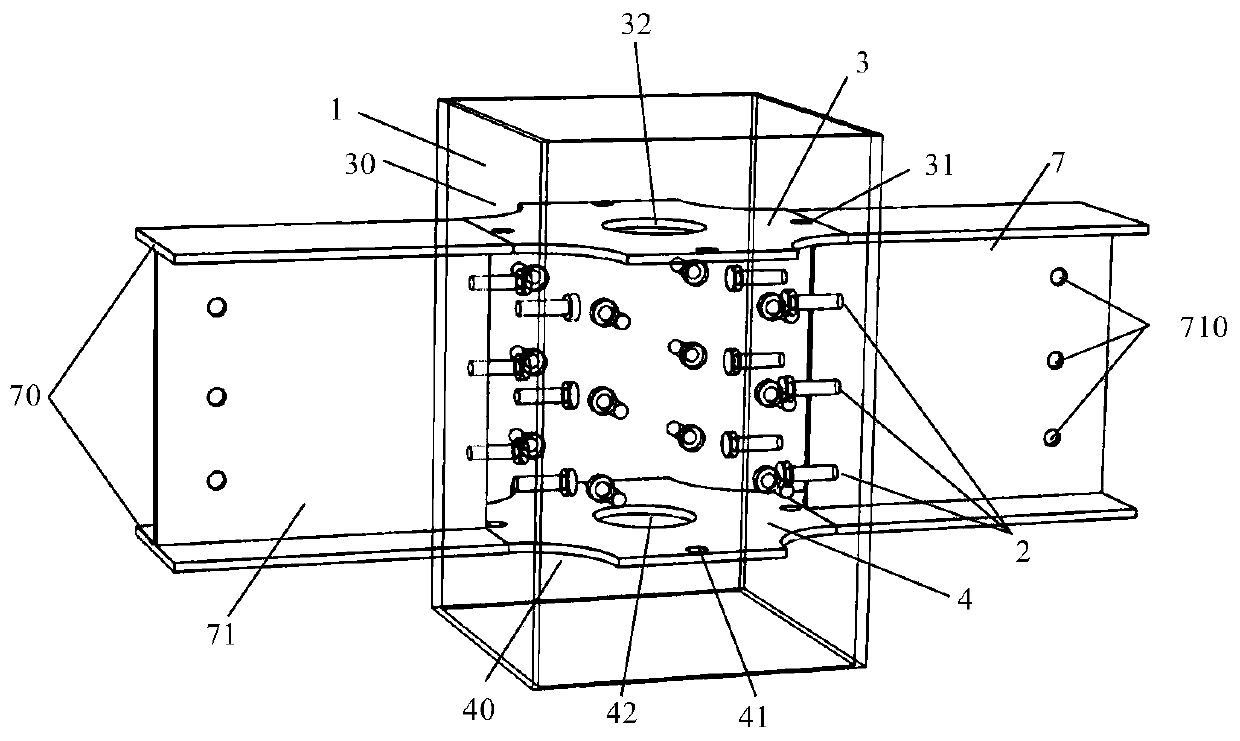
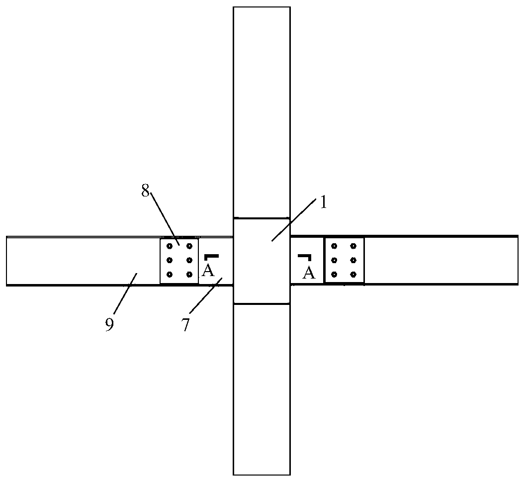
[0028] see Figure 1 to Figure 5 , a connection node between a prefabricated concrete column and a steel beam with an inner partition, the node includes an outer steel sleeve 1 fixed in the node area, a steel corbel 7, an upper inner partition 3 and a lower inner partition 4, said The outer steel casing 1 is fixed at the position corresponding to the prefabricated concrete column and the node area, and a structure cooperating with the concrete is arranged in the outer steel casing 1, and the upper inner partition 3 and the lower inner partition 4 are all arranged in the outer steel casing 1, the upper inner partition 3 is welded to the inner side wall of the outer steel casing 1 at the position corresponding to the top of the steel beam and t...


PUM


Abstract

The invention discloses a precast concrete column and steel beam connecting joint with inner partition plates. The joint comprises a steel-encased sleeve fixed in a joint area, the steel-encased sleeve is fixed at the position, corresponding to the joint area, of a precast concrete column, the upper inner partition plate and the lower inner partition plate are arranged in the steel-encased sleeve,the upper inner partition plate and the lower inner partition plate are welded to the inner side of the steel-encased sleeve plate at the positions, corresponding to the joint area, of the top and the bottom of a steel beam, the upper inner partition plate and the lower inner partition plate each are provided with a longitudinal bar penetrating structure and a concrete pouring hole, the steel-encased sleeve and a reinforcement cage of the precast concrete column are pre-buried in a concrete solid of the precast concrete column, the part, corresponding to the steel-encased sleeve, of the reinforcement cage of the precast concrete column is composed of longitudinal bars, the outer side face of the steel-encased sleeve is flush with the outer side face of the column, and a steel corbel connected with the steel beam is welded to the outer side face, corresponding to the steel beam, of the steel-encased sleeve. The precast concrete column and steel beam connecting joint is simple in structure and convenient to assemble, has good mechanical properties, is safe and reliable, and has good integrality.

Description

technical field [0001] The invention belongs to the technical field of building structures, in particular to a connection node between a prefabricated concrete column and a steel beam with an inner partition. Background technique [0002] As the development situation of my country's construction industry changes, the concept of building a city is not only to pursue modernization, but to pay more attention to green, environmental protection, humanities, intelligence and livability. Prefabricated buildings have the characteristics of green construction and environmental protection and high efficiency. Therefore, , Promoting the development of prefabricated buildings has become the top priority of the construction industry. The frame structure has the advantages of flexible layout, large indoor space, reasonable structural force, and clear force transmission. It is widely used in industrial and civil building structures, and is also one of the main structural forms of prefabrica...

Claims


Application Information

Patent Timeline
Patent Type & Authority Applications(China)
IPC IPC(8): E04B1/58
CPCE04B1/185
Inventor 张锡治李星乾章少华渠桂金
Owner TIANJIN UNIV RES INST OF ARCHITECTRUAL DESIGN & URBAN PLANNING
Why Eureka
Try Eureka