Supercharge Your Innovation With Domain-Expert AI Agents!

Decentralized cup-shaped cylinder and swash plate axial piston pump supported by rolling bearings

A rolling bearing, decentralized technology, applied in the components of pumping devices for elastic fluids, multi-cylinder pumps, variable displacement pump components, etc., can solve the problems of slipper failure, reduced pump reliability, slipper wear and other issues , to reduce the moment of inertia, improve reliability and reduce friction

Active Publication Date: 2017-07-25
XI AN JIAOTONG UNIV
View PDF6 Cites 0 Cited by
  • Summary
  • Abstract
  • Description
  • Claims
  • Application Information

AI Technical Summary

Problems solved by technology

[0002] At present, the common swash plate axial piston pump is generally composed of cylinder block, plunger, swash plate, transmission shaft, etc. During the operation of the pump, due to the friction between the sliding shoe and the swash plate, energy loss will be caused. , and due to the relative sliding between the sliding shoe and the swash plate, it is easy to cause the wearing of the sliding shoe, resulting in the failure of the sliding shoe and reducing the reliability of the pump
[0003] In the traditional floating cup plunger pump, the floating cup is in a floating state, which is easy to cause leakage under high pressure, which improves the material performance requirements and processing requirements, and there is a certain angle between the floating cup and the transmission shaft, and there is a large gap during the rotation process. vibration

Method used


Image

  • Decentralized cup-shaped cylinder and swash plate axial piston pump supported by rolling bearings
  • Decentralized cup-shaped cylinder and swash plate axial piston pump supported by rolling bearings
  • Decentralized cup-shaped cylinder and swash plate axial piston pump supported by rolling bearings

Examples


Embodiment Construction

[0014] The present invention will be described in detail below in conjunction with the accompanying drawings.

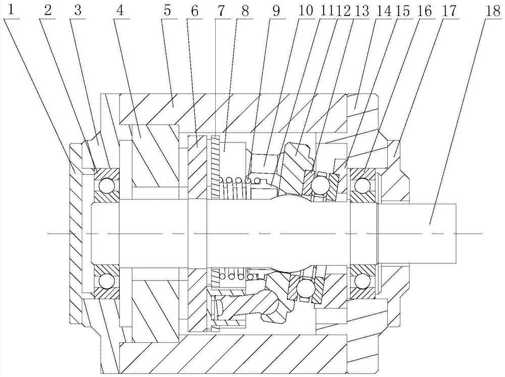
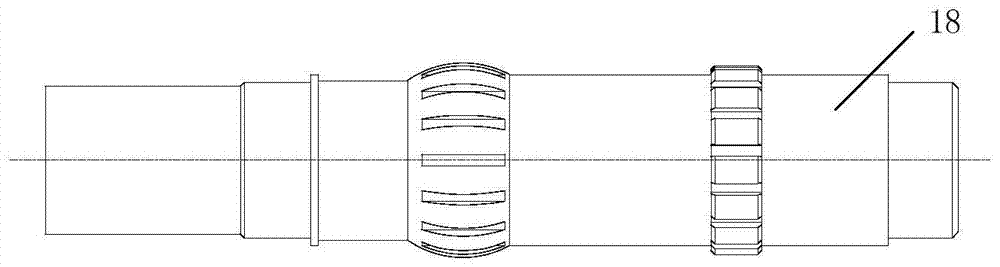
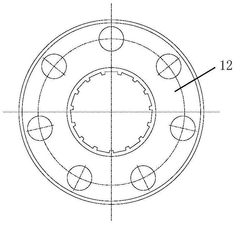
[0015] refer to figure 1 , figure 2 , image 3 , Figure 4 and Figure 5 , a swash plate axial piston pump supported by a decentralized cup-shaped cylinder and rolling bearings, including a drive shaft 18, the left and right ends of the drive shaft 18 are installed on the left end cover 3 through the first bearing 2 and the second bearing 16 respectively And on the right end cap 14, the left end cap 3, the right end cap 14 and the shell 5 are screwed together, and the first sealing end cap 1 and the second sealing end cap 17 are respectively installed on the outside of the left end cap 3 and the right end cap 14, and the driving The right side of the middle part of the shaft 18 is connected with the swash plate 12 through a drum-shaped spline, the left end surface of the swash plate 12 is connected with several plungers 10 through a ball joint, the right end sur...


PUM


Abstract

A swash plate type axial piston pump supported by a distributed cup-shaped cylinder block and rolling bearings, including a drive shaft, the left and right ends of the drive shaft are mounted on the left and right end covers, and the left and right end covers are fixed with the casing to drive the The right side of the middle part of the shaft is connected with the swash plate, the left end face of the swash plate is connected with several plungers through ball joints, the right end face of the swash plate is fixed on the fixed swash plate through rolling bearings, and the fixed swash plate is fixed on the right end cover; the drive shaft The left side of the middle part of the oil cup is connected with the oil cup mounting plate, the left side of the oil cup mounting plate is connected with the distribution assembly, the right side of the oil cup mounting plate is installed with several oil cups through the connecting piece, the oil cup is connected with the sliding end of the plunger, the swash plate In contact with the swash plate support block, the oil cup mounting plate and the oil cup pressing plate are in contact, and the two ends of the spring are respectively connected to the oil cup pressing plate and the swash plate supporting block. By simultaneously driving the oil cup mounting plate and the swash plate to rotate, Cooperate with the distribution mechanism to realize the oil suction and discharge of the pump, which has the advantages of compact structure and reliable transmission.

Description

technical field [0001] The invention belongs to the technical field of plunger pumps, in particular to a swash plate axial plunger pump supported by a distributed cup-shaped cylinder body and rolling bearings. Background technique [0002] At present, the common swash plate axial piston pump is generally composed of cylinder block, plunger, swash plate, transmission shaft, etc. During the operation of the pump, due to the friction between the sliding shoe and the swash plate, energy loss will be caused. , and due to the relative sliding between the sliding shoe and the swash plate, it is easy to cause the wearing of the sliding shoe, resulting in the failure of the sliding shoe and reducing the reliability of the pump. [0003] In the traditional floating cup plunger pump, the floating cup is in a floating state, which is easy to cause leakage under high pressure, which improves the material performance requirements and processing requirements, and there is a certain angle b...

Claims


Application Information

Patent Timeline
Patent Type & Authority Patents(China)
IPC IPC(8): F04B1/12F04B53/16F04B53/00
Inventor 赵升吨董朋张晨阳韩晓兰杨红伟赵永强
Owner XI AN JIAOTONG UNIV
Features
  • R&D
  • Intellectual Property
  • Life Sciences
  • Materials
  • Tech Scout
  • Unparalleled Data Quality
  • Higher Quality Content
  • 60% Fewer Hallucinations
Learn More