
Suspension oil cylinder and crane

A technology for suspending oil cylinders and cylinder barrels, which is applied in the direction of load suspension components, transportation and packaging, fluid pressure actuation devices, etc., which can solve problems such as poor adaptability and achieve good sealing effects

Inactive Publication Date: 2016-02-17
XUZHOU HEAVY MASCH CO LTD
View PDF4 Cites 1 Cited by
  • Summary
  • Abstract
  • Description
  • Claims
  • Application Information

AI Technical Summary

Problems solved by technology

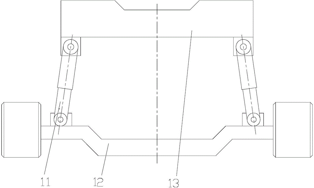
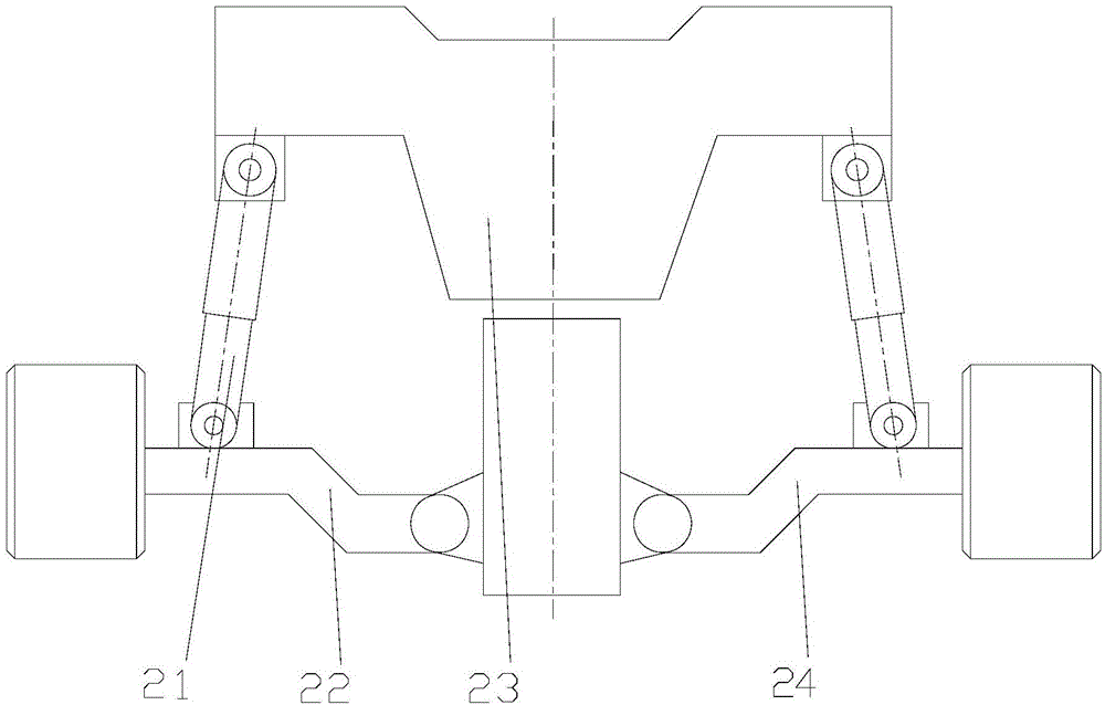
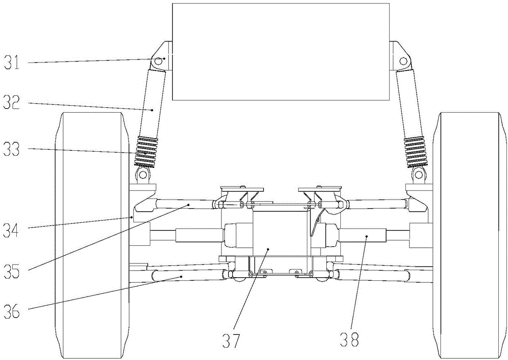
[0018] One of the objectives of the present invention is to propose a suspension cylinder and a crane equipped with the suspension cylinder, which solves the technical problem of poor adaptability to complex and severe working conditions in the prior art

Method used


Image

  • Suspension oil cylinder and crane
  • Suspension oil cylinder and crane
  • Suspension oil cylinder and crane

Examples


Embodiment 1

[0064] Such as Figure 6 ~ Figure 7 As shown, the suspension oil cylinder provided by the embodiment of the present invention includes a cylinder barrel 59, a piston rod 512 and a shock absorber, and the shock absorber includes an anti-falling body (preferably an end cover 52, the bottom surface or the side surface of the end cover 52 A layer of elastic material can also be provided or coated, and the elastic material can be rubber), connecting seat 53, flexible pad 54 (preferably rubber pad) and ball joint bearing inner ring 55, wherein: connecting seat 53 forms the ball joint bearing outer ring. A piston 515 can be provided at the end of the piston rod 512 , for example, the piston 515 can be provided at the end of the piston rod 512 .

[0065] The connection seat 53 , the flexible pad 54 and the inner ring 55 of the ball joint bearing are all provided with connection through holes. The anti-off body abuts against the part of the connecting seat 53 away from the cylinder ba...

Embodiment 2

[0083] Such as Figure 8 with Figure 9 As shown, this embodiment is basically the same as Embodiment 1, and the difference is that in this embodiment, the anti-detachment body (preferably end cap 52) can be connected through a detachable connection structure (preferably with such as Image 6 The anti-loosening bolts 51 shown in the same structure or similar) are connected with the piston rod 64, the piston rod 64 is fixedly connected with the inner protective shell 62, and the cylinder barrel 63 is fixedly connected with the outer protective shell 61. The inner protective shell 62 is sheathed outside the cylinder 63 , and the cylinder 63 is interposed between the inner protective shell 62 and the piston 65 at the end of the piston rod 64 . The outer protective shell 61 is sheathed outside the inner protective shell 62 , and the inner protective shell 62 can slide relative to the cylinder barrel 63 and the outer protective shell 61 .


PUM


Abstract

The invention discloses a suspension oil cylinder and a crane, and relates to the technical field of engineering machines. The technical problem that the adaptive capacity to the complex and serious working condition is poor in the prior art is solved. The suspension oil cylinder comprises a cylinder barrel, a piston rod and a vibration attenuation support, the vibration attenuation support comprises an anti-separation body, a connecting base, a flexible mat and a spherical hinge bearing inner ring, and the connecting base, the flexible mat and the spherical hinge bearing inner ring are each provided with a connecting through hole; the anti-separation body abuts against a part, far away from the cylinder barrel or the piston rod, of the connecting base and is connected one of the cylinder barrel or the piston rod through a detachable connecting structure; and the flexible mat is arranged between a part of area of the connecting base and a part of area of the spherical hinge bearing inner ring and connected with the part of area of the connecting base and the part of area of the spherical hinge bearing inner ring. The crane comprises the suspension oil cylinder. The suspension oil cylinder and the crane are used for improving the adaptive capacity to the complex and serious working condition.

Description

technical field [0001] The invention relates to the technical field of engineering machinery, in particular to a suspension oil cylinder and a crane provided with the suspension oil cylinder. Background technique [0002] Suspension is a general term for all force-transmitting connection devices between the vehicle frame (or load-bearing body) and the axle (or wheel) and the connected components. The main function of the suspension is to transmit the force between the wheel and the frame All forces and moments, and ease the impact of the car when driving on uneven roads, attenuate the vibration of the bearing system (or understood as vibration) caused by it, so as to ensure the ride comfort of the car. Suspension is mainly composed of elastic elements, shock absorbers, guide mechanisms and stabilizer bars. Suspension can be divided into independent suspension and non-independent suspension. The axle is a device that is connected to the frame (or load-bearing body) through ...

Claims


Application Information

Patent Timeline
IPC IPC(8): F15B15/14F15B15/20B66C13/00
Inventor 单增海赵玉峰东权朱磊梁静文宋建军
Owner XUZHOU HEAVY MASCH CO LTD
Learn More