Speed reducer with anti-backlash structure

A technology of reducer and anti-backlash, applied in the direction of belt/chain/gear, transmission parts, gear transmission, etc., can solve the problem of increasing gear gap, and achieve the effect of eliminating gear matching gap and avoiding noise increase

Inactive Publication Date: 2016-02-17
QIJIANG YONGYUE GEAR
View PDF8 Cites 4 Cited by
  • Summary
  • Abstract
  • Description
  • Claims
  • Application Information

AI Technical Summary

Problems solved by technology

[0004] In view of this, the object of the present invention is to provide a reducer with an anti-backlash structure to solve the technical problem that the gear clearance of the reducer gear in the prior art will increase during long-term use

Method used


Image

  • Speed reducer with anti-backlash structure
  • Speed reducer with anti-backlash structure

Examples


Embodiment Construction

[0011] The present invention will be further described below in conjunction with the accompanying drawings and embodiments.

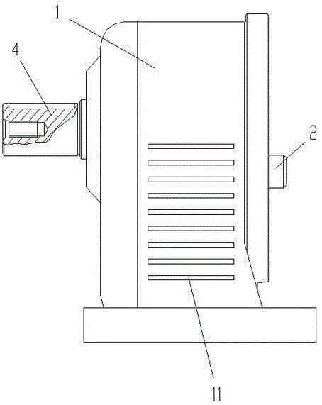
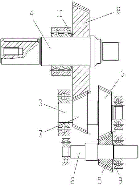
[0012] As shown in the figure, the reducer with anti-backlash structure in this embodiment includes a reducer casing 1 and a gear transmission mechanism arranged in the reducer casing, and the gear transmission mechanism includes an input shaft arranged on the reducer casing through a bearing 2. The intermediate shaft 3 and the output shaft 4, the input shaft is provided with a first bevel gear 5, the intermediate shaft is provided with a second bevel gear 6 meshing with the first bevel gear and a diameter smaller than the second bevel gear The third bevel gear 7, the output shaft is provided with a fourth bevel gear 8 engaged with the third bevel gear; the second bevel gear and the third bevel gear are fixedly matched with the intermediate shaft in the axial direction; A bevel gear and the input shaft are slidingly fitted in the axial direction, and an...


PUM


Abstract

The invention discloses a speed reducer with an anti-backlash structure. The speed reducer with the anti-backlash structure comprises a speed reducer outer shell and a gear transmission mechanism. The gear transmission mechanism comprises an input shaft, a middle shaft and an output shaft, wherein the input shaft is provided with a first bevel gear, the middle shaft is provided with a second bevel gear and a third bevel gear engaged with the first bevel gear, and the output shaft is provided with a fourth bevel gear engaged with the third bevel gear. A first butterfly spring used for applying axial thrust force on the first bevel gear is arranged between the first bevel gear and a bearing. A second butterfly spring used for applying axial thrust force on the fourth bevel gear is arranged between the fourth bevel gear and the bearing. According to the speed reducer with the anti-backlash structure, when the gears are abraded, the butterfly springs automatically push the first bevel gear and the fourth bevel gear to move in the axial direction, and therefore a gear matching gap caused by friction abrasion is eliminated. The problems of increase of noise and impact force on the gears and the like caused by the increase of the gear matching gap can be avoided.

Description

technical field [0001] The invention relates to a speed reduction device, in particular to a speed reducer. Background technique [0002] The reducer is a transmission device used to convert the high-speed low-torque power output by the electric motor or internal combustion engine into low-speed high-torque output. [0003] The reducer is generally composed of the reducer casing and the gear transmission mechanism set in the reducer casing. During the transmission process of the gear, its tooth surface is prone to friction and wear. Friction and wear will lead to an increase in the fit gap between the gears, which in turn will lead to gear meshing. When the noise increases and the impact force on the gear increases, the acceleration gear is damaged. Contents of the invention [0004] In view of this, the object of the present invention is to provide a reducer with an anti-backlash structure to solve the technical problem in the prior art that the gear clearance of the red...

Claims


Application Information

Patent Timeline
Patent Type & Authority Applications(China)
IPC IPC(8): F16H1/22F16H57/12F16H57/028
CPCF16H1/22F16H57/028F16H57/12
Inventor 张集胜王才张文初崔家川蓝来
Owner QIJIANG YONGYUE GEAR
Why Eureka
Try Eureka