Movable tooth cam mechanism capable of achieving single-shaft constant-speed input and double-shaft variable-speed swing output

A technology of cam mechanism and input shaft, which is applied in the direction of wobble plate transmission, belt/chain/gear, mechanical equipment, etc., and can solve problems such as poor bearing capacity, swing angle range, and angular velocity limitation of mechanism size, etc.

Inactive Publication Date: 2016-02-17
BEIJING UNIV OF TECH
View PDF6 Cites 10 Cited by
  • Summary
  • Abstract
  • Description
  • Claims
  • Application Information

AI Technical Summary

Problems solved by technology

In addition, due to the influence of the swing angle error, the range of the swing angle, the size of the mechanism, and the ang

Method used


Image

  • Movable tooth cam mechanism capable of achieving single-shaft constant-speed input and double-shaft variable-speed swing output
  • Movable tooth cam mechanism capable of achieving single-shaft constant-speed input and double-shaft variable-speed swing output
  • Movable tooth cam mechanism capable of achieving single-shaft constant-speed input and double-shaft variable-speed swing output

Examples


Embodiment approach 1

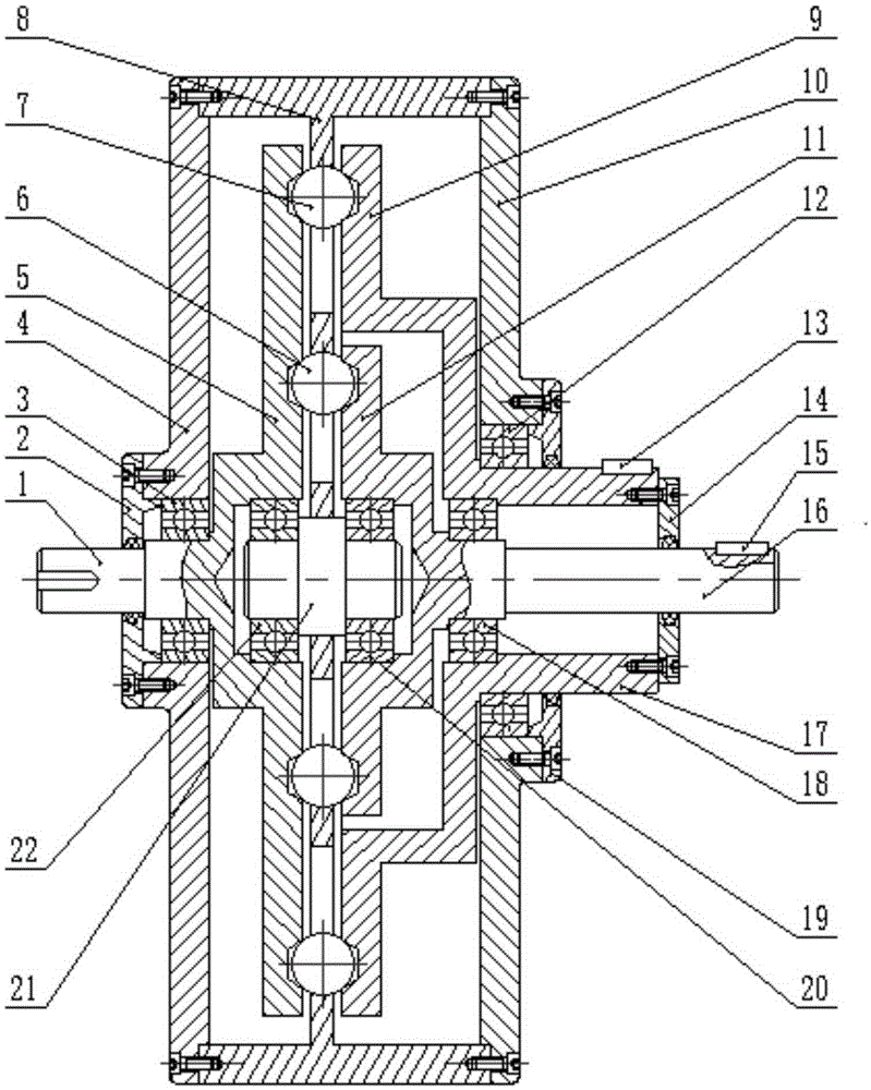
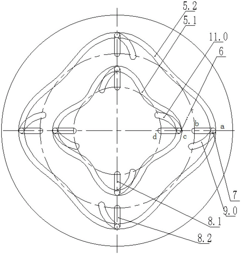
[0038] Such as figure 1 , Figure 2-1 to Figure 2-7 As shown, the mechanism includes an input shaft 1, an input disk 5, an inner layer steel ball 6, an outer layer steel ball 7, a movable tooth frame 8, an inner layer oscillating disk 11, an outer layer oscillating disk 9, an inner layer output shaft 16, an outer Layer output shaft 17. The input shaft 1 and the input disc 5 are fixedly connected to form a shock wave; the movable rack 8 is fixedly connected to the frame, and the inner steel balls 6 and outer steel balls 7 are evenly distributed on the movable rack 8 along the circumferential direction In the radial groove of the input disk, and always in the staggered area of ​​the inner tooth profile groove 5.1 of the input disc and the inner oscillating disc tooth profile groove 11.0, and the staggered area of ​​the outer tooth profile groove 5.2 of the input disc and the outer oscillating disc tooth profile groove 9.0 Area; the inner oscillating disc 11 and the outer oscil...

Embodiment approach 2

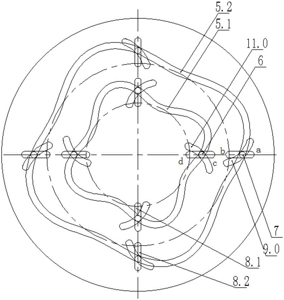
[0041] This embodiment is the same as Embodiment 1 in terms of the transmission principle of the mechanism, and the difference lies in the swing angles of the inner and outer oscillating plates of Embodiment 2 are different. The outline of the component is Figure 3-2 to Figure 3-5 shown.

Embodiment approach 3

[0043] This embodiment is the same as Embodiment 1 in terms of the transmission principle of the mechanism, and the difference lies in the swing rules of the inner and outer oscillating disks of Embodiment 3 are different. The outline of the component is Figure 4-2 to Figure 4-5 shown.


PUM


Abstract

The invention provides a movable tooth cam mechanism capable of achieving single-shaft constant-speed input and double-shaft variable-speed swing output, and belongs to the technical field of mechanical transmission. The mechanism comprises an input shaft, an input plate, inner steel balls, outer steel balls, a movable tooth rack, an inner swing plate, an outer swing plate, an inner output shaft, an outer output shaft and a machine frame. The input shaft and the input plate are fixedly connected into a whole to constitute a shock wave device. The movable tooth rack is fixedly connected to the machine frame. The inner steel balls are evenly distributed in inner radial grooves distributed in the movable tooth rack in the circumferential direction respectively and are located in interlacing areas of an inner transverse tooth profile groove of the input plate and transverse tooth profile grooves of the inner swing plate respectively all the time, and the outer steel balls are evenly distributed in outer radial grooves distributed in the movable tooth rack in the circumferential direction respectively and are located in interlacing areas of an outer transverse tooth profile groove of the input plate and transverse tooth profile grooves of the outer swing plate respectively all the time. The inner swing plate is fixedly connected with the inner output shaft, and the outer swing plate is fixedly connected with the outer output shaft. Through the movable tooth cam mechanism, single-shaft constant-speed input and double-shaft simultaneous variable-speed swing output can be achieved, and the swing direction, the swing angle, the swing law and the bearing capacity can be combined according to practical situations; on the premise that using conditions are met, the functions of the mechanism are maximized.

Description

technical field [0001] The invention relates to a movable-tooth cam mechanism with single-axis constant-speed input and double-axis variable-speed swing output, belonging to the technical field of mechanical transmission. Background technique [0002] In many aspects such as textile machinery, printing machinery, agricultural machinery, and automated office equipment, there is a particularly large demand for specific and regular oscillating motions, and these oscillating motions are mostly realized by means of cam mechanisms. In some cases where multiple sets of swing motions are required, the requirements have to be met by increasing the number of cam mechanisms. In addition, due to the influence of the swing angle error, the range of the swing angle, the size of the mechanism, and the angular velocity of the main and driven parts of the cam mechanism are greatly limited, and its bearing capacity is relatively poor. Therefore, it is particularly important to design a mecha...

Claims


Application Information

Patent Timeline
IPC IPC(8): F16H23/10
CPCF16H23/10
Inventor 李剑锋赵宏伟
Owner BEIJING UNIV OF TECH
Why Eureka
Try Eureka