Reaction cavity and reaction equipment

A technology of a reaction chamber and a shielding member is applied in the field of reaction chambers and reaction equipment, and can solve the problems of poor film uniformity, influence on the properties of deposited films, insufficient and uniform diffusion of reaction gas, etc., so as to achieve good film, improve diffusion effect and uniformity. sexual effect

Active Publication Date: 2016-02-17
BEIJING NAURA MICROELECTRONICS EQUIP CO LTD
View PDF4 Cites 3 Cited by
  • Summary
  • Abstract
  • Description
  • Claims
  • Application Information

AI Technical Summary

Problems solved by technology

[0005] The present invention provides a reaction chamber and reaction equipment, which are used to solve the problem that the gas intake method in the prior art prevents the reaction gas from being sufficiently uniformly diffused into the reaction chamber, so that the properties of the deposited film on the edge of the wafer are affected, and the obtained The problem of poor film uniformity

Method used


Image

  • Reaction cavity and reaction equipment
  • Reaction cavity and reaction equipment
  • Reaction cavity and reaction equipment

Examples


Embodiment Construction

[0026] In order to enable those skilled in the art to better understand the technical solution of the present invention, the reaction chamber and reaction equipment provided by the present invention will be described in detail below with reference to the accompanying drawings.

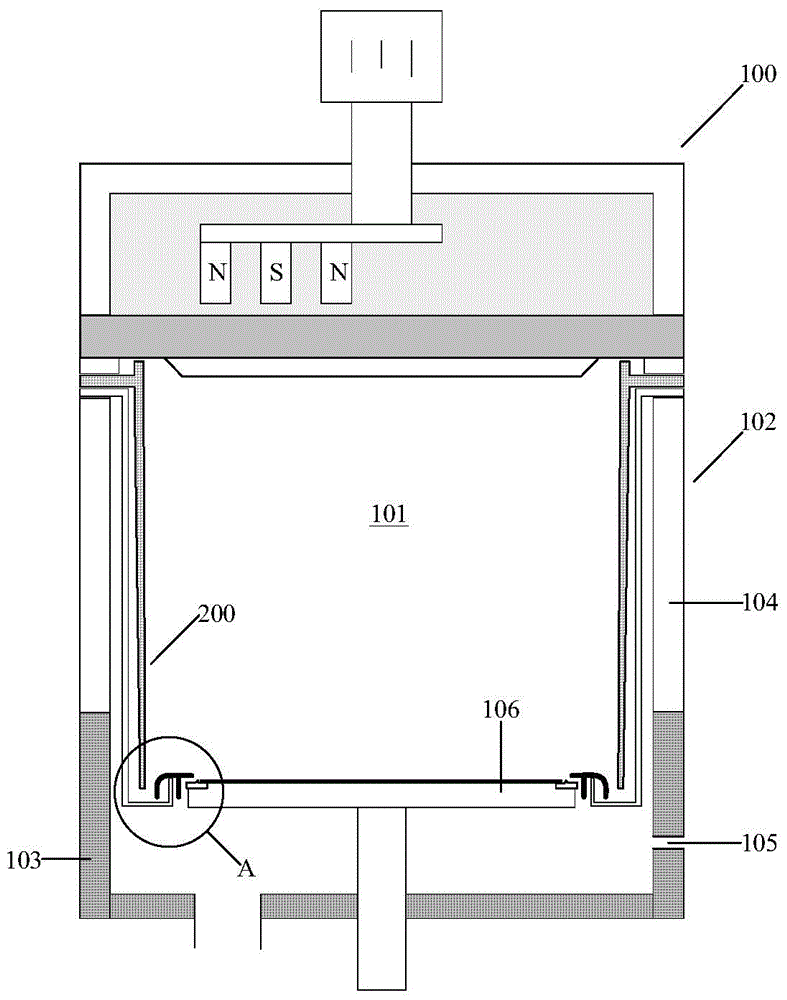
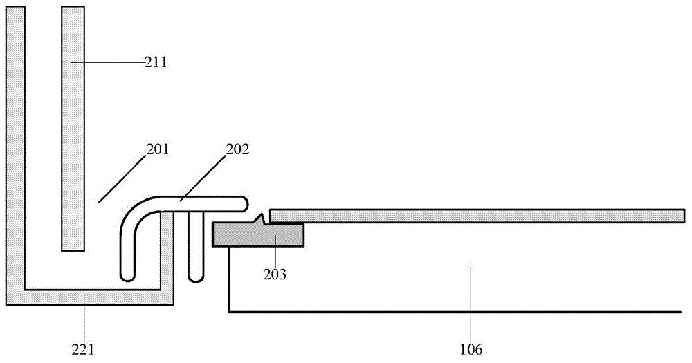
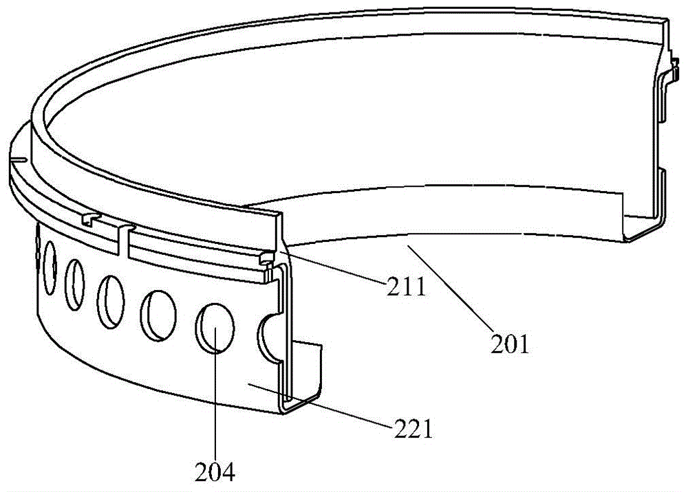
[0027] Figure 4 A schematic structural diagram of a reaction chamber provided by an embodiment of the present invention. Such as Figure 4 As shown, the reaction chamber 100 includes a process component 200 . Preferably, the reaction chamber 100 further includes a chamber wall 102 and a base 106 . The process component 200 and the base 106 surround the processing area 101 . The chamber wall 102 includes a chamber body 103 and side walls 104 . Figure 5 for Figure 4 An enlarged view of the structure of part B of the reaction chamber shown. Such as Figure 5 As shown, the process assembly 200 includes a shroud 201 . The shield 201 includes an upper shield 211 and a lower shield 221 . The lower...


PUM


Abstract

The invention provides a reaction cavity and reaction equipment. The reaction cavity comprises a pedestal for bearing a processed workpiece and a process assembly. The process assembly contains a shielding member having an upper shielding member and a lower shielding member; the bottom of the lower shielding member has a U-shaped groove structure encircling the bottom of the upper shielding member; and at least one first pore is formed in the lower part of one side, approaching the side wall of the reaction cavity, of the U-shaped groove. According to the technical scheme, the first pore is formed in the bottom of the lower shielding member by approaching an inlet of an air source, so that reaction gas can be led into a processing area directly. Therefore, the reaction gas can be diffused to the reaction chamber uniformly and fully, thereby influencing the proportion component of the reaction gas in the reaction cavity and improving the diffusion effect and uniformity of the reaction gas entering the reaction cavity and thus obtaining a better thin film.

Description

technical field [0001] The invention relates to the technical field of semiconductor technology, in particular to a reaction chamber and reaction equipment. Background technique [0002] In the manufacture of integrated circuits and displays, a substrate, such as a semiconductor wafer or a display panel, is placed in a reaction chamber, and process conditions in the reaction chamber are set to deposit material on or etch the substrate. A typical reaction chamber includes a peripheral wall surrounding the plasma region, a substrate holder for supporting the substrate, a gas source for providing process gases within the chamber, a gas energizer for applying energy to the gas to process the substrate, and Vent for maintaining pressure. The reaction chamber may include sputtering (PVD), chemical vapor deposition (CVD) and etch chambers. [0003] In the sputtering process, a process gas including an inert gas and / or a reactive gas is supplied into the reaction chamber, and an e...

Claims


Application Information

Patent Timeline
Patent Type & Authority Applications(China)
IPC IPC(8): H01L21/67
Inventor 杨玉杰
Owner BEIJING NAURA MICROELECTRONICS EQUIP CO LTD
Why Eureka
Try Eureka