Front shell component and metal front shell structure of electronic equipment

A technology of electronic equipment and front shell, which is applied in the field of electronic equipment, can solve the problems that are contrary to the development needs of light and thin electronic equipment, and the thickness of electronic equipment increases, and achieve the effect of meeting the development needs of light and thin and reducing the thickness

Inactive Publication Date: 2016-02-17
XIAOMI INC
View PDF5 Cites 5 Cited by
  • Summary
  • Abstract
  • Description
  • Claims
  • Application Information

AI Technical Summary

Problems solved by technology

[0003] However, since the metal shield needs to cover the outer surface of the device to be shielded, when assembled into the electronic device, the thickness of the electronic device will increase, which is contrary to the development requirements of thinner and lighter electronic devices

Method used


Image

  • Front shell component and metal front shell structure of electronic equipment
  • Front shell component and metal front shell structure of electronic equipment
  • Front shell component and metal front shell structure of electronic equipment

Examples


Embodiment 1

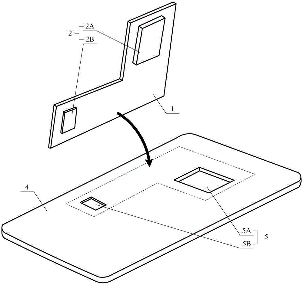
[0038] Figure 2A It is a three-dimensional schematic diagram of a metal front shell structure and a printed circuit board of an electronic device according to one of the exemplary embodiments, such as Figure 2A As shown, the electronic device is provided with a printed circuit board 1 adjacent to the metal front shell structure 4, and the side of the printed circuit board 1 close to the metal front shell structure 4 is provided with a number of devices to be shielded 2 (such as devices to be shielded) 2A and the device to be shielded 2B); where:

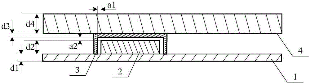
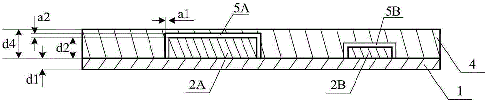
[0039] The metal front shell structure 4 is provided with a number of grooves 5 corresponding to the device to be shielded 2 (for example, groove 5A corresponding to the device to be shielded 2A, and groove 5B corresponding to the device to be shielded 2B), and each The opening position and size specifications of a groove 5 are matched to the corresponding device to be shielded 2, so that when the metal front shell structure 4 and the ...

Embodiment 2

[0045] Figure 3A Is a cross-sectional view of an electronic device according to the second exemplary embodiment, such as Figure 3A As shown, this embodiment provides a front housing assembly of an electronic device, and the front housing assembly includes:

[0046] The metal front shell structure 4 is provided with a number of through holes 5'(such as through holes 5'A and through holes 5'A and 2B) corresponding to the device to be shielded 2 (such as the device to be shielded 2A and the device to be shielded 2B) one-to-one Through hole 5'B etc.);

[0047] The metal sheet 6 closes the end of the through holes 5'far away from the printed circuit board 1 in the electronic device, so that the metal sheet 6 and the through holes 5'form corresponding groove structures (in the figure Not labeled); wherein, the metal sheet 6 is also electrically connected to the metal front shell structure 4;

[0048] Wherein, the opening position and size specifications of each through hole 5'are matche...

Embodiment 3

[0058] Figure 4 Is a cross-sectional view of an electronic device according to the third exemplary embodiment, such as Figure 4 As shown, the current case assembly includes a number of metal sheets 6 (such as metal sheets 6A and metal sheets 6B, etc.) corresponding to a number of through holes 5'(such as through holes 5'A and through holes 5'B, etc.), and each When a metal sheet 6 respectively closes the end of the corresponding through hole 5'far away from the printed circuit board 1 to form a corresponding groove structure, each metal sheet 6 can be respectively embedded in the corresponding through hole 5', and the metal The outer surface of the sheet 6 and the side of the metal front shell structure 4 away from the printed circuit board 1 are on the same plane.

[0059] Therefore, in this embodiment, by embedding several metal sheets 6 into the through holes 5', Figure 2B The structure shown in the first embodiment is similar; however, compared with the structure shown in t...


PUM


Abstract

The invention relates to a front shell component and metal front shell structure of electronic equipment. The front shell component and the metal front shell structure can replace electromagnetic shields in the electronic equipment and conduce to reducing the thickness of the electronic equipment. The front shell component comprises the metal front shell structure and a metal sheet, wherein a plurality of through holes corresponding to devices to be shielded on a printed circuit board in the electronic equipment one to one are formed in the metal front shell structure; the metal sheet closes the ends, far away from the printed circuit board, of the plurality of through holes, so that the metal sheet and the plurality of through holes form a plurality of corresponding groove structures; the metal sheet is also electrically connected to the metal front shell structure; and the forming position and dimension of each through hole are matched with the corresponding device to be shielded, so that when the metal front shell structure and the printed circuit board are assembled in the electronic equipment in a mutual fitting manner, the groove structure corresponding to each through hole can contain the corresponding device to be shielded and keeps a preset interval from the contained device to be shielded.

Description

Technical field [0001] The present disclosure relates to the technical field of electronic devices, and in particular to the front shell assembly and metal front shell structure of the electronic device. Background technique [0002] In related technologies, it is necessary to add corresponding electromagnetic shielding covers to the CPU and radio frequency chip waiting shielding devices in the electronic equipment to meet the electromagnetic radiation requirements and ensure the normal operation of the electronic equipment. [0003] However, since the metal shielding cover needs to cover the outer surface of the device to be shielded, the thickness of the electronic device will increase when it is assembled into the electronic device, which is contrary to the development demand of light and thin electronic devices. Summary of the invention [0004] The present disclosure provides a front shell assembly and a metal front shell structure of an electronic device to solve the deficienc...

Claims


Application Information

Patent Timeline
Patent Type & Authority Applications(China)
IPC IPC(8): H05K5/02H05K5/04
Inventor 裴远涛司新伟庞成林
Owner XIAOMI INC
Why Eureka
Try Eureka