Heat pipe with primary conductive circuit and preparation process thereof

A technology of conductive circuit and preparation process, which is applied in the preparation process of heat pipe and the field of heat pipe with native conductive circuit, can solve the problems of short life, high junction temperature of LED, incapability of large-scale application of automobile headlights, etc., and achieves the reduction of thermal resistance. Effect

Inactive Publication Date: 2016-02-17
余原生
View PDF5 Cites 4 Cited by
  • Summary
  • Abstract
  • Description
  • Claims
  • Application Information

AI Technical Summary

Problems solved by technology

[0005] The welding method has the smallest thermal resistance but the process is complicated, the bonding method has the largest thermal resistance but the process is simple, and the mechanical fixing method has the thermal resistance between the two and the process is more complicated
[0006] For example: LED car headlights have to match the optical focus of the reflector. 20-40w LEDs must be concentrated on multiple non-directional planes and curved surfaces on a 5-6mm wide 100mm2 surface area geometry. Due to the light output of the LED and There is a corresponding relationship between life and junction temperature (the higher the junction temperature, the smaller the light output of the LED and the shorter the life), and the heat flux density of this application is as high as 40w / cm2, and the heat must be transferred out of the reflector to dissipate heat. The technical solution is to weld the LED to the copper substrate and then fix the copper substrate to the copper isothermal rod covered with heat pipe or the solid copper isothermal rod by welding or mechanical connection to transfer the heat out of the reflector to dissipate heat. Due to many links, especially the existence of the heat conduction bottleneck of the copper substrate, the junction temperature of this high heat flux LED is high, which affects the light output and lifespan. As a result, the current LED car headlights cannot be used on a large scale.

Method used


Image

  • Heat pipe with primary conductive circuit and preparation process thereof

Examples


Embodiment Construction

[0028] The following will clearly and completely describe the technical solutions in the embodiments of the present invention with reference to the accompanying drawings in the embodiments of the present invention. Obviously, the described embodiments are only some, not all, embodiments of the present invention. Based on the embodiments of the present invention, all other embodiments obtained by persons of ordinary skill in the art without creative efforts fall within the protection scope of the present invention.

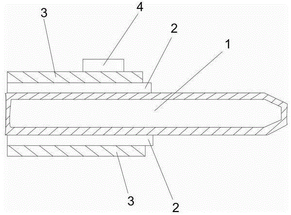
[0029] A heat pipe with a primary conductive circuit, comprising: a heat pipe 1, a thermally conductive insulating layer 2, a circuit layer 3 and an electronic device 4, the thermally conductive insulating layer 2 is wrapped on one end or several positions of the heat pipe 1, and the circuit layer 3 is covered on the thermally conductive insulating layer 2, the electronic device 4 is fixed on the circuit layer 3, and the fixing method can be welding, bonding, mechan...


PUM


Abstract

The invention provides a heat pipe with a primary conductive circuit. The heat pipe comprises a heat pipe body, a heat-conducting insulating layer, a circuit layer and an electronic device, wherein the heat-conducting insulating layer covers one end of the heat pipe body or cover a plurality of positions of the heat pipe body; the circuit layer covers the heat-conducting insulating layer; the electronic device is fixed on the circuit layer; heat emitted when the electronic device works is transmitted to the heat pipe body from the bottom through the circuit layer and the heat-conducting insulating layer; the heat can be rapidly transmitted to other heat dissipation devices connected with the heat pipe body with low resistance through the heat pipe body, so as to be dissipated, while electric connection is realized through the circuit layer; and the invention further provides a preparation process of the heat pipe with the primary conductive circuit.

Description

technical field [0001] The invention relates to the field of electronic devices, in particular to a heat pipe with primary conductive lines, and also relates to a preparation process for the heat pipe with primary conductive lines. Background technique [0002] Existing electronic products have to deal with small volume and high power density applications. The best technical solution is to use PCB with heat conduction function to meet the electrical connection requirements of electronic devices and meet the requirements of heat conduction and heat dissipation. The connection requirements must also meet the requirements of heat conduction and partial heat dissipation. In order to quickly take away the heat from the heat-conducting PCB, it is currently the best solution to use heat pipes to transfer heat. Distributed passively to places with low temperatures. [0003] Based on the above schemes, the heat-conducting PCBs that can be used at present include aluminum-based, copp...

Claims


Application Information

Patent Timeline
Patent Type & Authority Applications(China)
IPC IPC(8): H05K7/20
Inventor 余原生
Owner 余原生
Why Eureka
Try Eureka