Fan shroud assembly

A technology for fans and shields, applied in the field of fan shield assemblies, can solve the problems of increased noise, increased pressure variation, and non-symmetrical shape of the fan shield assembly 20, and achieves the effects of reducing noise and preventing sticking or freezing.

Active Publication Date: 2016-02-17
HANON SYST
View PDF6 Cites 7 Cited by
  • Summary
  • Abstract
  • Description
  • Claims
  • Application Information

AI Technical Summary

Problems solved by technology

[0012] However, if figure 2 As shown, the shape of the fan shroud assembly 20 for a vehicle is generally not a symmetrical shape, and because of the limitation of space for installation to the vehicle, the space between the tapered mouth 21 forming the anti-eddy current serrations and the position of the outer edge of the shroud become

Method used


Image

  • Fan shroud assembly
  • Fan shroud assembly
  • Fan shroud assembly

Examples


Embodiment Construction

[0044] best practice

[0045] Hereinafter, the fan shroud assembly according to the present invention as described above will be described in detail with reference to the accompanying drawings.

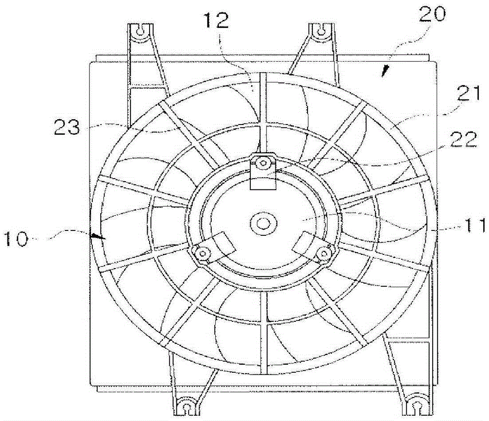
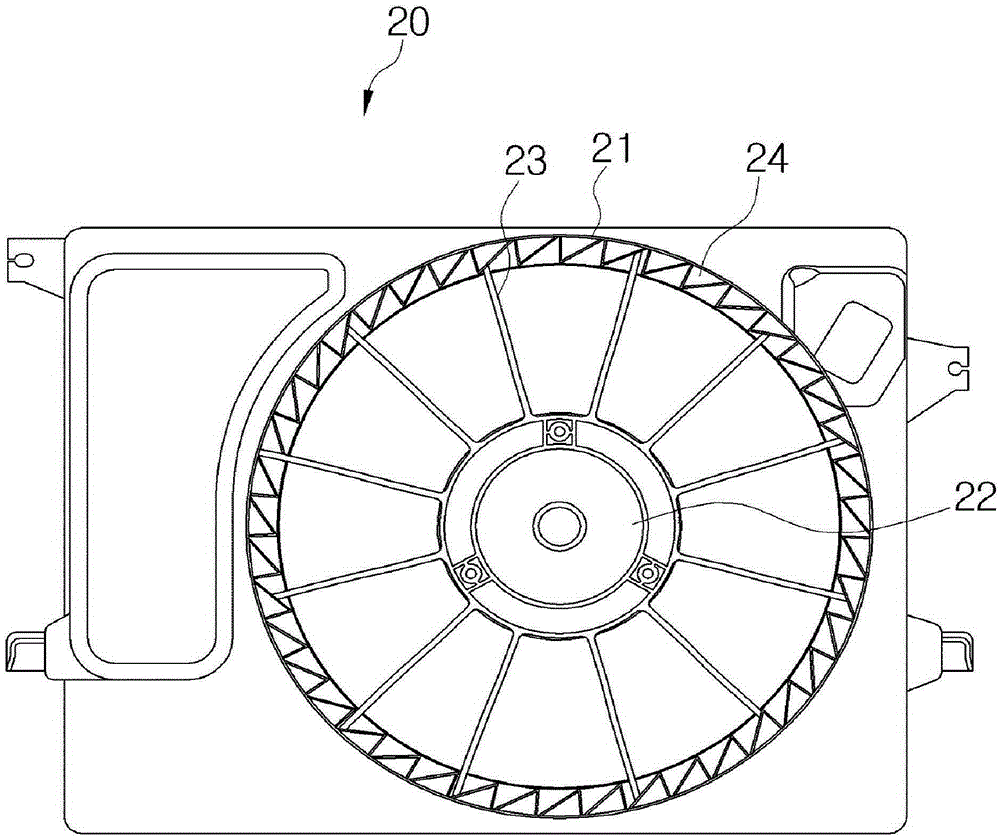
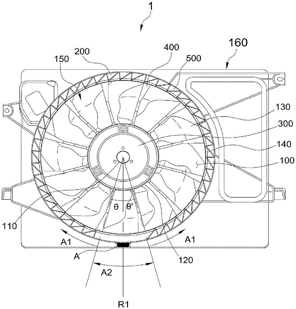
[0046] like image 3 As shown, the fan shroud assembly 1 according to the present invention is generally composed of a fan 150 and a shroud 160 .

[0047] First, the fan 150 is a rotary fan that transmits blown air to the heat exchanger of the vehicle while being rotated by the motor 110, and includes: a hub 120, blades 130 and a fan ring 140, and the shroud 160 includes: a cone Shaped mouth 200 , motor assembly part 300 and fixing piece 400 .

[0048] First, in order to move air by means of the fan 150, the tapered opening 200 forms an air blowing portion 100, which is a space in which a predetermined central area of ​​a plenum portion is hollow.

[0049] The electrode assembly part 300 is a part for assembling the motor for driving the fan 150 , and is located in the central area...


PUM


Abstract

The present invention relates to a fan shroud assembly and, more specifically, to a fan shroud assembly comprising: vortex-preventing saw-teeth which are arranged along a predetermined inner circumferential surface of a ventilating unit so as to maintain a predetermined gap with a blade end part or a band end part of a fan, and which are formed in a saw-toothed shape, wherein both a first area in which the vortex-preventing saw-teeth are formed and a second area from which the vortex-preventing saw-teeth are removed are formed, thereby generating vortexes of ventilated air due to a reduction in pressure fluctuation and thus effectively reducing noise.

Description

technical field [0001] The present invention relates to a fan shroud assembly, in particular to a fan shroud assembly comprising anti-eddy current sawtooth and formed with a first area and a second area, wherein the anti-eddy current sawtooth is along the inner peripheral surface of the air supply part The predetermined area is arranged at a predetermined distance from the end of the fan blade or the end of the fan ring and is formed in a zigzag shape, the first area is an area formed with anti-eddy current serrations, and the second area is an area with anti-eddy current serrations removed Therefore, the transferred air generates a vortex as the amount of pressure fluctuation becomes smaller, thereby effectively reducing noise. Background technique [0002] In the engine that generates the actual driving force of the vehicle, a large amount of heat energy is generated in the process of converting chemical energy into kinetic energy. If such heat energy is excessively gener...

Claims


Application Information

Patent Timeline
IPC IPC(8): F04D29/54
CPCF01P5/06F01P11/12F04D29/164F04D29/526F04D19/002F04D29/663F04D25/08F04D29/52
Inventor 郑宇烈林车孺权容成赵庆锡
Owner HANON SYST
Why Eureka
Try Eureka