Automatic assembling device and method for lamp strips of LED lamp tubes

A technology of LED light tubes and LED light strips is applied in the field of manufacturing, which can solve the problems of reducing the working efficiency of glue dispensing and laminating machines, increasing manpower, etc., so as to achieve the effects of controllable assembly quality, improvement of work efficiency, and avoidance of assembly quality problems.

Active Publication Date: 2016-02-24
SHANGHAI RADIO EQUIP RES INST
4 Cites 29 Cited by

AI-Extracted Technical Summary

Problems solved by technology

However, this automatic dispensing and laminating machine needs to manually place the lamp tube in the lamp tube positioning de...

Method used

3, assembly quality is high: use automation means to carry out dispensing and the consistency of assembling is good, assembly quality is controllable; Can strictly control dispensing position and dispensing amount by precision dispensing valve, have guaranteed dispensing quality...

Abstract

The invention relates to an automatic assembling device for lamp strips of LED lamp tubes. The automatic assembling device comprises a feeding platform which is used for stacking glass tubes which are not assembled, an automatic lamp tube feeding mechanism, a lamp strip dispensing mechanism, a pressure holding mechanism and a discharging platform. The input end of the automatic lamp tube feeding mechanism is connected with the feeding platform, receives glass tubes on the feeding platform in sequence and transfers the glass tubes to corresponding positions. The lamp strip dispensing mechanism is adjacent to one side edge of the automatic lamp tube feeding mechanism, conducts dispensing on the LED lamp strips evenly and is inserted into the LED lamp strips into the corresponding glass tubes. The pressure holding mechanism is arranged above the automatic lamp tube feeding mechanism and presses the glass tubes so that the LED lamp strips can be stuck to the inner walls of the glass tubes so as to form LED lamp tubes. The discharging platform is connected with the output end of the automatic lamp tube feeding mechanism and receives the assembled LED lamp tubes. The invention further relates to an automatic assembling method for the lamp strips of the LED lamp tubes, and the method is achieved through the assembling device. According to the automatic assembling device and method for the lamp strips of the LED lamp tubes, automatic feeding and discharging of the LED lamp tubes can be achieved, automatic dispensing and assembling of the lamp strips can be achieved, and the lamp strip assembling quality and efficiency of the LED lamp tubes can be effectively improved.

Application Domain

Liquid surface applicatorsCoatings +1

Technology Topic

EngineeringLED lamp +1

Image

  • Automatic assembling device and method for lamp strips of LED lamp tubes
  • Automatic assembling device and method for lamp strips of LED lamp tubes
  • Automatic assembling device and method for lamp strips of LED lamp tubes

Examples

  • Experimental program(1)

Example Embodiment

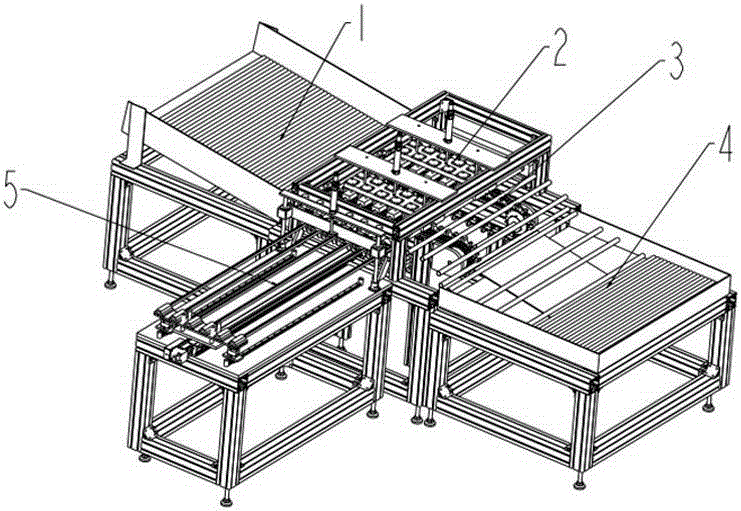
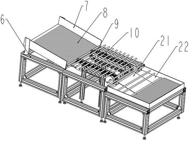
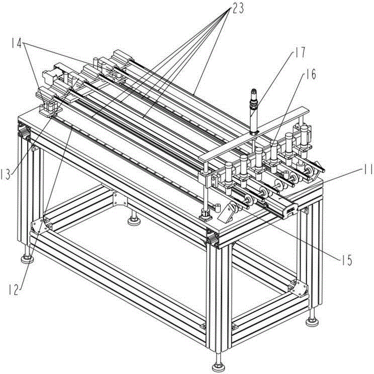
[0038] The following combination Figure 1 ~ Figure 4 , A preferred embodiment of the present invention will be described in detail.
[0039] Such as figure 1 As shown, the automatic assembly device for the LED lamp strip provided by the present invention includes: a feeding platform 1 for stacking unassembled glass tubes 8; an automatic lamp feeding mechanism 3, the input end of which is connected to the The feeding platform 1 is connected to the feeding platform 1 and is used to sequentially receive the glass tubes 8 on the feeding platform 1 and move them to the corresponding position; the lamp tape dispensing mechanism 5 is connected to the side of the lamp automatic feeding mechanism 3 The sides are adjacent to each other and are used to apply glue to the LED light strip 23 evenly and insert it into the corresponding glass tube 8; the pressure holding mechanism 2 is arranged above the automatic lamp tube feeding mechanism 3 for pressing The glass tube 8 makes the LED light strip 23 adhere to the inner wall of the glass tube 8 to form an LED light tube; the unloading platform 4 is connected to the output end of the light tube automatic feeding mechanism 3 for receiving completion Assembled LED tube.
[0040] The automatic assembling device for the light strip of the LED light tube further includes a bracket 6 which is arranged under the feeding platform 1, the light tube automatic feeding mechanism 3, the light strip dispensing mechanism 5 and the unloading platform 4 , Has a supporting role.
[0041] Such as figure 2 As shown, the feeding platform 1 includes: a feeding frame 7, which is obliquely arranged on the support 6 and connected to the input end of the automatic lamp feeding mechanism 3 for stacking Assembled glass tube 8.
[0042] Such as figure 2 As shown, the automatic lamp tube feeding mechanism 3 includes: a plurality of chain transmission modules 9 which are respectively arranged on the bracket 6 in parallel and spaced apart; a plurality of material holders 10, which are gear-shaped, are respectively arranged on each chain transmission module 9, and ensure that the tooth grooves of a number of material holders 10 are aligned horizontally, and the chain drive module 9 drives synchronous cyclic movement; when the tooth grooves of the material holder 10 are aligned with the glass tube at the discharge port of the material feeding frame 7 At 8 o'clock, the glass tube 8 simultaneously rolls into the transversely aligned tooth grooves of several pallets 10 under the action of gravity, and is driven by the chain drive module 9 to move the glass tube 8 to the corresponding position and then stop.
[0043] In this embodiment, two chain transmission modules 9 and two material holders 10 are adopted, and each material holder 10 is respectively arranged on the chain transmission module 9 to load the glass tube 8.
[0044] Such as image 3 As shown, the light strip dispensing mechanism 5 includes: a light strip linear transmission module, which is arranged on the bracket 6, and one end is adjacent to one side of the light tube automatic feeding mechanism 3, and Aim at the glass tube 8 located on the material tray 10, the light strip linear transmission module is used to place the LED light strip 23, drive it to be transmitted along a straight line and inserted into the corresponding glass tube 8 located on the material tray 10; It is arranged at the end adjacent to one side of the light strip linear transmission module and the automatic lamp tube feeding mechanism 3, and when the LED light strip 23 is driven by the light strip linear transmission module to be conveyed along a straight line, glue is evenly applied to it.
[0045] The light strip linear transmission module includes: a plurality of linear guide rails 12, which are respectively arranged on the bracket 6 in parallel and spaced apart, and one end of each linear guide rail 12 is opposite to one side of the automatic lamp feeding mechanism 3 Adjacent; a plurality of light strip holding rods 13, the bottom end of each light strip holding rod 13 is respectively arranged on each linear guide 12, the middle is connected to each other to form a whole, the top is provided with a slot; each slot is respectively Align the corresponding glass tubes 8 on the material tray 10, and put the LED light strips 23 into the respective slots, so that the LED light strips 23 are also aligned with the glass tubes 8; the bracket 15 is set in each straight line The guide rail 12 is adjacent to one side of the automatic lamp feeding mechanism 3, and is used to support and hold the top of each slot; the linear motion drive module 11 is arranged on the lamp belt supporting rod 13 in the middle , Used to drive and connect a number of light strip holder rods 13 forming a whole to reciprocate linearly along each linear guide 12, after inserting the LED light strip 23 in the card slot into each glass tube 8 on the material holder 10, drive The lamp belt supporting rod 13 exits the glass tube 8.
[0046] The dispensing module includes: a plurality of dispensing valves 16 arranged above the bracket 15 and respectively aligned with each LED light strip 23; a dispensing cylinder 17, which is respectively connected with a plurality of dispensing valves 16 for driving A number of dispensing valves 16 move vertically up and down; while the LED light strip 23 is driven by the light strip carrier rod 13 to be conveyed to the glass tube 8 along the linear guide 12, the dispensing cylinder 17 drives the multiple dispensing valves 16 vertically downwards Move, and align each LED light strip 23 closely, and apply glue evenly on its upper surface; after finishing the glue application, the glue cylinder 17 drives several glue valves 16 to move vertically upwards.
[0047] In this embodiment, 6 light strips supporting rods 13 are used, respectively equipped with 6 linear guide rails 12 and 6 dispensing valves 16, which means that 6 LED light strips 23 can be glued at the same time, and Insert into the corresponding glass tube 8 on the material tray, that is, in this embodiment, one batch can complete the assembly of 6 LED tubes at the same time.
[0048] The light strip glue dispensing mechanism 5 further includes: at least two first jacking cylinders 14, which are arranged on the light strip support rods 13 located on both sides, and are used to drive and connect a plurality of light strip support rods forming a whole. 13 Perform vertical up and down movements.
[0049] Such as Figure 4 As shown, the pressure holding mechanism 2 includes a frame 18, which is arranged on the bracket 6 and is located above the lamp tube automatic feeding mechanism 3, and one end is adjacent to the lamp tape dispensing mechanism 5. The bracket 25, which is set on the frame 18, and located at the opposite end of the adjacent end of the light strip dispensing mechanism 5; the bracket 25 is provided with a number of positioning holes, each positioning hole is aligned in the material support 10 上corresponding glass tube 8; when the several light strip holder rods 13 of the glue dispensing mechanism 5 are driven by the linear motion drive module 11, they drive the LED light strip 23 along each linear guide 12 into each glass tube on the material holder 10 8 inside, the top of the slot of each light strip supporting rod 13 exposes the glass tube 8 and is inserted into each positioning hole of the supporting block 25, supported by the supporting block 25; at least two second lifting cylinders 24, It is set on the frame 18 and located on both sides of the bracket 25 to drive the bracket 25 to move vertically up and down; when the glued LED light strip 23 is driven by the light strip support rod 13 to insert the corresponding glass After the tube 8 is inside, the first lifting cylinder 14 drives a plurality of lamp belt supporting rods 13 which are connected to form a whole to move upwards, while at the same time the second lifting cylinder 24 drives the bracket 25 and drives the slots inserted into the positioning holes to move upwards , So as to hold up the LED light strip 23 in the card slot to make it close to the inner wall of the glass tube 8; the pressure holding cylinder 19, which is fixedly arranged on the frame 18; the pressure block 20, which is connected to the The pressure cylinder 19 is connected and moves vertically and vertically under the drive of the pressure-holding cylinder 19; when the glued LED light strip 23 is held up against the inner wall of the glass tube 8, the pressure-holding cylinder 19 drives the pressure block 20 vertically downwards The glass tube 8 is moved and pressed to make the LED light strip 23 adhere to the inner wall of the glass tube 8; after the bonding is completed, the pressure holding cylinder 19 drives the pressing block 20 to move vertically upward.
[0050] In this embodiment, the positioning holes on the bracket 25 must be provided with 6 correspondingly, so as to support the top ends of the slots of the 6 light strip holder rods 13 respectively.
[0051] Such as figure 2 As shown, the unloading platform 4 includes: an unloading frame 22, which is arranged on the support 6 and connected to the output end of the automatic lamp feeding mechanism 3 for stacking to complete assembly The LED tube; the guide plate 21, which is obliquely arranged at the bottom of the material frame 22, and is in contact with the material holder 10.
[0052] The present invention also provides an automated assembly method for the light strip of the LED tube, which is realized by the above-mentioned automated assembly device, and includes the following steps:
[0053] S1. Stack the unassembled glass tubes 8 in the feeding frame 7 of the feeding platform 1;
[0054] S2. The several chain transmission modules 9 of the automatic lamp feeding mechanism 3 synchronously drive the material holders 10 respectively arranged on them to cyclically move; when the tooth grooves of the material holders 10 are aligned with the glass at the discharge port of the feeding frame 7 When tube 8, the glass tube 8 is simultaneously rolled into the transversely aligned tooth grooves of a plurality of material holders 10 under the action of gravity, so that several glass tubes 8 are automatically loaded onto the material holder 10 in turn;
[0055] S3. Under the control of the chain drive module 9, move several glass tubes 8 on the material holder 10 to align with each corresponding light belt material holder rod assembly 13 and then stop;
[0056] S4. Put the LED light strips 23 into the slots of several light strip support rods 13 respectively;
[0057] S5. The linear motion drive module 11 drives and connects a number of light strip supporting rods 13 formed as a whole to run along each linear guide 12, and drives the LED light strip 23 to move in the direction of the glass tube 8;
[0058] S6. The dispensing cylinder 17 drives several dispensing valves 16 to move vertically downwards, making them close to each LED light strip 23. As the LED light strip 23 moves, each dispensing valve 16 uniformly spreads glue on On the corresponding LED light strip 23;
[0059] S7. After the glue application is completed, several dispensing valves 16 are closed and the dispensing stops, and the dispensing cylinder 17 drives the dispensing valves 16 to move vertically upwards; at this time, a number of LED light strips 23 that have been glued are already in the light strip holder Driven by the material rod 13, it is completely inserted into each glass tube 8 on the material holder 10;
[0060] S8. The top of the slot of each light strip supporting rod 13 exposes the glass tube 8 and is inserted into each positioning hole of the supporting block 25, and is supported by the supporting block 25; the first lifting cylinder 14 is drivingly connected to form a number of integrated lights The supporting rod 13 moves upwards, and the second lifting cylinder 24 drives the supporting block 25 and drives the slots inserted into the positioning holes to move upwards, holding up the LED strip 23 in the slot to make it close to the glass tube The inner wall of 8;
[0061] S9. The pressure holding cylinder 19 drives the pressure block 20 to move vertically downward and press the glass tube 8 so that the LED light strip 23 is close to the inner wall of the glass tube 8 and pressure is maintained for 3 to 8 seconds, so that the LED light strip 23 is adhered to On the inner wall of the glass tube 8; in this embodiment, the pressure holding time can be 5 seconds;
[0062] S10. After the pressure-holding time is over, the pressure-holding cylinder 19 drives the pressure block 20 to move vertically upwards, the first jacking cylinder 14 drives the plurality of light strip support rods 13 connected to form a whole to move downwards, while the second jacking cylinder 24 drives The bracket 25 also drives the slots inserted into the positioning holes to move downwards. At this time, the LED light strip 23 is adhered to the inner wall of the glass tube 8 to form an LED tube, which is separated from the slot;
[0063] S11. The linear motion drive module 11 drives and connects a number of light strip support rods 13 forming a whole to run along each linear guide 12 and exit the corresponding glass tube 8, returning to the initial position to wait for the next light strip assembly;
[0064] S12. Under the control of the chain drive module 9, move a number of assembled LED tubes on the material tray 10 in the direction of the feeding platform 4. When the LED tubes touch the inclined guide plate 21, they will be separated The pallet 10 rolls down along the guide plate 21 and is stacked in the blanking frame 22 to complete the automatic blanking;
[0065] S13. Return to execute S2 and proceed to the automatic assembly of the next batch of LED tubes.
[0066] Compared with the manual assembly method in the prior art, the automatic assembly device and assembly method of the LED lamp strip provided by the present invention have the following significant advantages and beneficial effects:
[0067] 1. High efficiency: The present invention can simultaneously dispense and assemble multiple LED light strips, which greatly improves work efficiency;
[0068] 2. Saving manpower: the loading of unassembled glass tubes, the dispensing assembly of LED light strips, and the unloading of the assembled LED light tubes are all realized by an automated assembly device, and only the LED light strips need to be placed manually The loading work of the clamping slot of the light belt supporting rod greatly simplifies the labor intensity and saves manpower;
[0069] 3. High assembly quality: the consistency of dispensing and assembly using automated means is good, and the assembly quality is controllable; the dispensing position and amount can be strictly controlled through the precision dispensing valve, ensuring the dispensing quality and consistency, and avoiding The assembly quality problems caused by uneven manual dispensing;
[0070] 4. High flexibility: The present invention can adjust the distance between several chain drive modules to adapt to the assembly of LED tubes of various lengths.
[0071] Although the content of the present invention has been described in detail through the above preferred embodiments, it should be recognized that the above description should not be considered as limiting the present invention. After those skilled in the art have read the above content, various modifications and substitutions to the present invention will be obvious. Therefore, the protection scope of the present invention should be defined by the appended claims.

PUM

no PUM

Description & Claims & Application Information

We can also present the details of the Description, Claims and Application information to help users get a comprehensive understanding of the technical details of the patent, such as background art, summary of invention, brief description of drawings, description of embodiments, and other original content. On the other hand, users can also determine the specific scope of protection of the technology through the list of claims; as well as understand the changes in the life cycle of the technology with the presentation of the patent timeline. Login to view more.

Similar technology patents

Parts procurement method and apparatus

InactiveUS20040148227A1improve efficiency
Owner:DAIKIN IND LTD

MIMO-OFDM transmitter

InactiveUS20070253504A1improve efficiencyreduce time
Owner:FUJITSU LTD

Systems and methods for providing treatment planning

InactiveUS20050182654A1high quality of careimprove efficiency
Owner:ALIGN TECH

Lawful interception in wireline broadband networks

ActiveUS20100086119A1improve efficiencyincrease compatibility
Owner:TELEFON AB LM ERICSSON (PUBL)

Classification and recommendation of technical efficacy words

  • Improve work efficiency
  • Improve efficiency

Cooperation service platform facing different source data

InactiveCN101174957AImprove management level and qualityImprove work efficiency
Owner:NANJING UNIV OF FINANCE & ECONOMICS

Screw drilling tool, vertical drilling tool testing method and well inclination simulation testing equipment

InactiveCN111594144AReduced height requirementsImprove work efficiency
Owner:DEZHOU UNITED GASOLINEEUM MACHINERY

Method for intelligent automatic identification of transmission circuit parts

Owner:INFORMATION COMM COMPANY STATE GRID SHANDONG ELECTRIC POWER +2

Keyboard spill-proofing mechanism

ActiveUS7030330B2minimize manufacturing costimprove work efficiency
Owner:LITE ON SINGAPORE PTE LTD

Video coding methods and apparatuses

ActiveUS7003035B2improve efficiencyreduce amount of data
Owner:MICROSOFT TECH LICENSING LLC

System and method for improving site operations by detecting abnormalities

InactiveUS20130027561A1improve efficiency
Owner:PANASONIC INTELLECTUAL PROPERTY MANAGEMENT CO LTD

Method and Apparatus of Adaptive Loop Filtering

ActiveUS20110274158A1improve efficiency
Owner:HFI INNOVATION INC
Why Eureka
Try Eureka