
A fan blade balance cutting machine

A technology for balancing cutting and fan blades, which is applied to metal processing machinery parts, manufacturing tools, positioning devices, etc., can solve problems such as low production efficiency, unbalanced fan dynamics, time-consuming and labor-intensive manufacturing methods, etc., to achieve fast cutting speed, Accurate cutting and smooth surface effect

Inactive Publication Date: 2019-06-14
DONGGUAN JIAJI SMART TECH CO LTD
View PDF9 Cites 4 Cited by
  • Summary
  • Abstract
  • Description
  • Claims
  • Application Information

AI Technical Summary

Problems solved by technology

[0002] Fan dynamic balance correction is an indispensable production process in the fan industry; when the fan is running at high speed, it will produce "biased" rotation and unbalanced vibration, which will greatly affect the service life of the product
[0003] The traditional way of correcting fan blades is to use detection equipment to detect one or more unbalanced points, and use special materials with glue to adhere to the inner wall of the magnetic ring and fan blades; usually such actions need to be completed many times, Time-consuming and labor-intensive, when the fan is used for a certain period of time, the "counterweight" material attached to the inner wall will fall off, which will affect the service life of the fan; quality problems will occur
[0004] Since the fan industry has been solving the dynamic imbalance of fans from ancient times to the present, it has always been to use the addition of counterweight materials to adjust the dynamic imbalance of the fan. Big, short fan life

Method used


Image

  • A fan blade balance cutting machine
  • A fan blade balance cutting machine
  • A fan blade balance cutting machine

Examples


Embodiment Construction

[0022] The following will clearly and completely describe the technical solutions in the embodiments of the present invention with reference to the accompanying drawings in the embodiments of the present invention. Obviously, the described embodiments are only some, not all, embodiments of the present invention. Based on the embodiments of the present invention, all other embodiments obtained by persons of ordinary skill in the art without making creative efforts belong to the protection scope of the present invention.

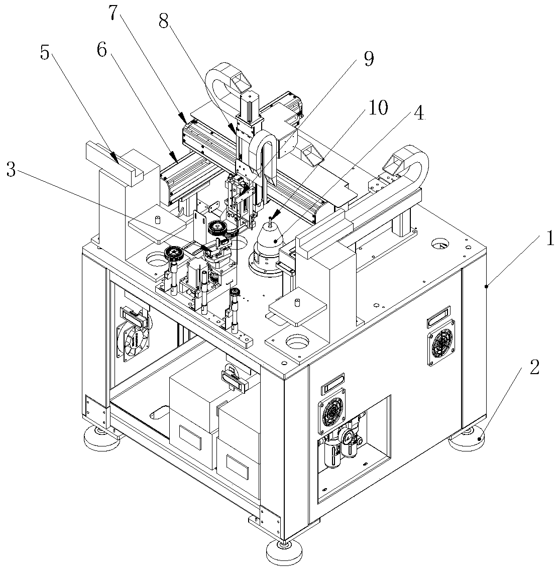
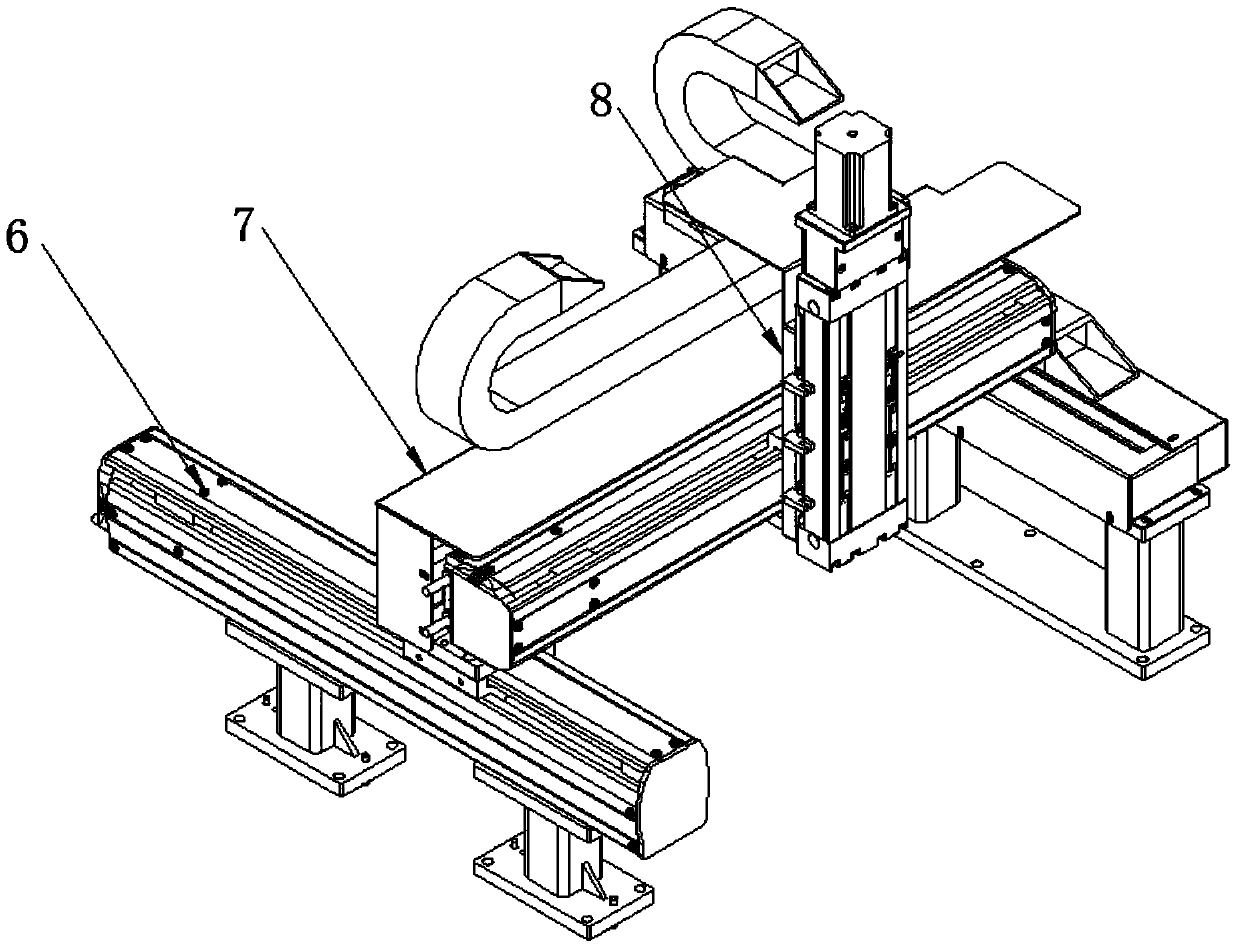
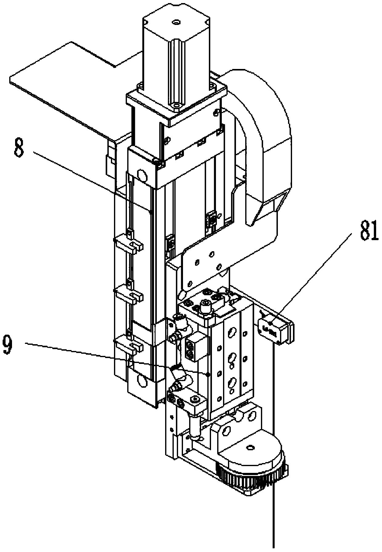
[0023] see Figure 1-7 , in an embodiment of the present invention, a fan blade balance cutting machine includes a body 1, a cutting tool 4, a center positioning mechanism 3, a balance detector 5 and a clamping cylinder 9, and four feet are evenly installed on the bottom of the body 1 2. The cutting tool 4 is fixedly installed on the top center of the body 1. The cutter head of the cutting tool 4 adopts a T-shaped milling cutter 10, and the cutting tool 4 is d...


PUM


Abstract

The invention discloses a fan blade balance cutting machine. The fan blade balance cutting machine comprises a machine body, a cutting tool, a central positioning mechanism, balance detectors and a clamping cylinder, wherein the cutting tool is arranged on the center of the top end of the machine body; the central positioning mechanism and the balance detectors are all arranged on the front side of the top end of the machine body; the rear side of the top end of the machine body is fixedly provided with X-axis moving modules which are symmetrical about the central positioning mechanism; a Y-axis moving module is arranged between the two X-axis moving modules in a sliding manner; a Z-axis moving module is movably arranged on the Y-axis moving module; and the X-axis moving modules, the Y-axis moving module and the Z-axis moving module are all movably provided with the clamping cylinder and a second position sensor. According to the cutting machine disclosed by the invention, multi-axis movement is adopted; unbalanced points of a fan are accurately cut by utilizing the cutting tool; the balance weight of a magnetic ring on the inner wall of a fan blade is reduced; the surface of the cut magnetic ring is smooth; the cutting is accurate; the cutting speed is high; and the problems of vibration and short service life caused by unbalanced fan rotation are solved.

Description

technical field [0001] The invention relates to the field of machinery, in particular to a blade balance cutting machine. Background technique [0002] Fan dynamic balance correction is an indispensable production process in the fan industry; when the fan is running at high speed, it will produce "biased" rotation and unbalanced vibration, which will also greatly affect the service life of the product. [0003] The traditional way of correcting fan blades is to use detection equipment to detect one or more unbalanced points, and use special materials with glue to adhere to the inner wall of the magnetic ring and fan blades; usually such actions need to be completed many times, It is time-consuming and labor-intensive. When the fan is used for a certain period of time, the "counterweight" material attached to the inner wall will fall off, which will affect the service life of the fan; quality problems will occur. [0004] Since the fan industry has been solving the dynamic i...

Claims


Application Information

Patent Timeline
Patent Type & Authority Patents(China)
IPC IPC(8): B23C3/00B23Q3/08B23Q1/25B23Q1/01
CPCB23C3/00B23Q1/015B23Q1/25B23Q3/08B23Q2703/04
Inventor 张来生石军宋旋
Owner DONGGUAN JIAJI SMART TECH CO LTD
Learn More