Calibration method for positional relation between paraxial type visual system and laser vibrating mirror machining system

A laser galvanometer and vision system technology, applied in laser welding equipment, metal processing equipment, manufacturing tools, etc., can solve the problems of bringing in, complex mechanical structure design, time-consuming adjustment process, etc., to achieve high-efficiency calibration accuracy and reduce calibration The effect of low efficiency and calibration accuracy

Inactive Publication Date: 2016-02-24
HUBEI UNIV OF TECH
View PDF8 Cites 33 Cited by
  • Summary
  • Abstract
  • Description
  • Claims
  • Application Information

AI Technical Summary

Problems solved by technology

The adjustment process is time-consuming and involves a lot of human fact

Method used


Image

  • Calibration method for positional relation between paraxial type visual system and laser vibrating mirror machining system
  • Calibration method for positional relation between paraxial type visual system and laser vibrating mirror machining system
  • Calibration method for positional relation between paraxial type visual system and laser vibrating mirror machining system

Examples


Embodiment Construction

[0020] In order to make the object, technical solution and advantages of the present invention clearer, the present invention will be further described in detail below in conjunction with the accompanying drawings and embodiments. It should be understood that the specific embodiments described here are only used to explain the present invention, not to limit the present invention.

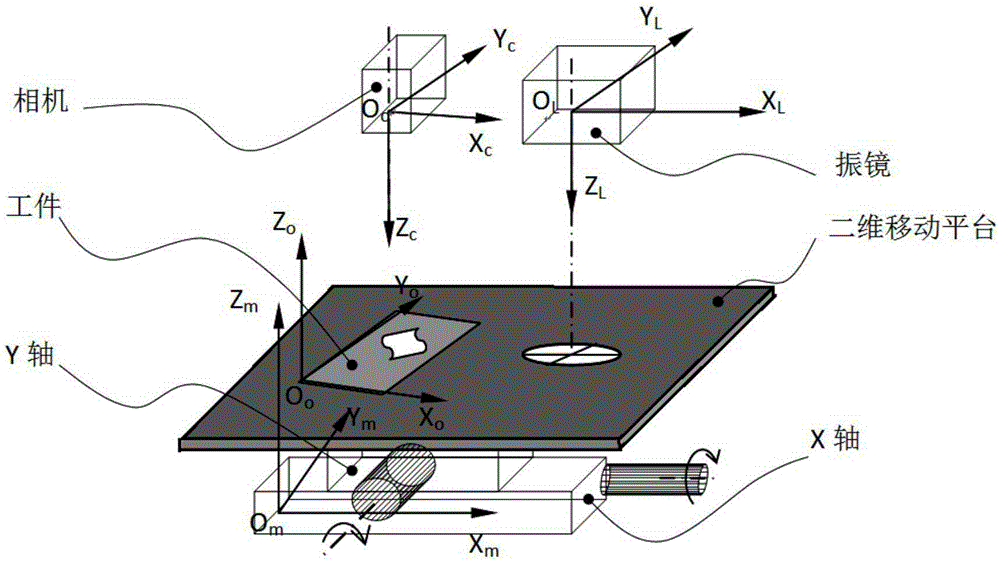
[0021] please see figure 1 with figure 2 , a method for calibrating the positional relationship between a paraxial vision system and a laser galvanometer processing system provided by the present invention is characterized in that it comprises the following steps:

[0022] Step 1: Establish a calibration camera coordinate system O c -X c Y c Z c and the galvanometer coordinate system O L -X L Y L Z L ; where, O c Indicates the optical center of the camera, O c Z c Coincident with the camera optical axis, O c x c Parallel to the horizontal direction of the camera pixel, O c Y c Para...


PUM


Abstract

The invention discloses a calibration method for the positional relation between a paraxial type visual system and a laser vibrating mirror machining system. The calibration method comprises the steps that a test-carving target is put in the field of view of a vibrating mirror, and the coordinates of a marked point in a vibrating mirror coordinate system at the moment are obtained; the test-carving target is put in the field of view of a calibration camera, and the coordinates of the marked point in the vibrating mirror coordinate system at the moment are obtained; according to the image of the marked point, in combination of a camera imaging principle, the coordinates of the initial position marked point in a calibration camera coordinate system are obtained; and the positional relation between the vibrating mirror coordinate system and the calibration camera coordinate system is represented through a matrix vector McL=[RcL, tcL], and based on the coordinates of the initial position marked point in the vibrating mirror coordinate system and the calibration camera coordinate system, the matrix vector is optimally obtained through a levenberg-marquardt (LM) method. According to the calibration method, no complex mechanical adjustment is needed, and the problems that the calibration efficiency and calibration precision are not high due to manual operation are solved. That is to say, the calibration method has the advantages of convenience, quickness, high efficiency and high calibration precision.

Description

technical field [0001] The invention belongs to the technical field of laser processing, in particular to a calibration method for the positional relationship between a paraxial vision system and a laser vibrating mirror processing system. Background technique [0002] In high-precision laser processing (such as etching, welding, etc.), the vision system is often used to measure the position and angle of the workpiece, and then guide the galvanometer or laser head to process according to the measurement results. [0003] The side-axis vision system is the most widely used in high-precision laser processing because it does not need to change the optical path and mechanical structure of the existing laser processing system. However, in order to improve the accuracy of laser processing, the field of view of laser processing and vision system is small, and the field of view of the two does not overlap. Even if they overlap, it is only at the edge of the field of view, and the di...

Claims


Application Information

Patent Timeline
IPC IPC(8): B23K26/03B23K26/042
CPCB23K26/032
Inventor 吴庆华陈慧何涛王正家
Owner HUBEI UNIV OF TECH
Why Eureka
Try Eureka