
A non-orthogonal structure casing processing method and fixture

A processing method and non-orthogonal technology, applied in the direction of manufacturing tools, metal processing equipment, metal processing machinery parts, etc., can solve the problem of installation positioning, clamping and alignment difficulties, installation edge and casing cylinder are not perpendicular, difficult Guarantee the processing quality of the casing and other issues, and achieve the effect of solving the installation and positioning difficulties of milling and turning composite processing, good application prospects, and ensuring processing quality

Active Publication Date: 2017-06-09
SHENYANG LIMING AERO-ENGINE GROUP CORPORATION
View PDF6 Cites 0 Cited by
  • Summary
  • Abstract
  • Description
  • Claims
  • Application Information

AI Technical Summary

Problems solved by technology

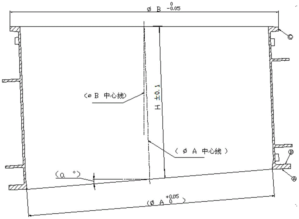
[0002] The shape of the non-orthogonal structure casing is as follows: figure 1 As shown, it is an important load-bearing part of the aero-engine. The non-orthogonal structure casing parts have a special structure. Positioning, clamping and alignment are difficult, and the process route is different from conventional processing methods. It is difficult to guarantee the processing quality of this type of casing with conventional processing methods

Method used

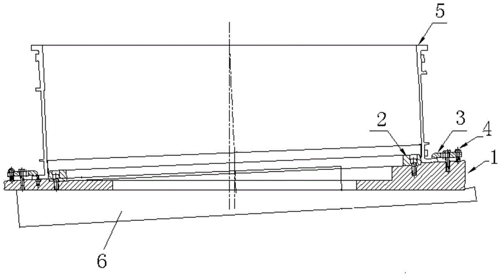
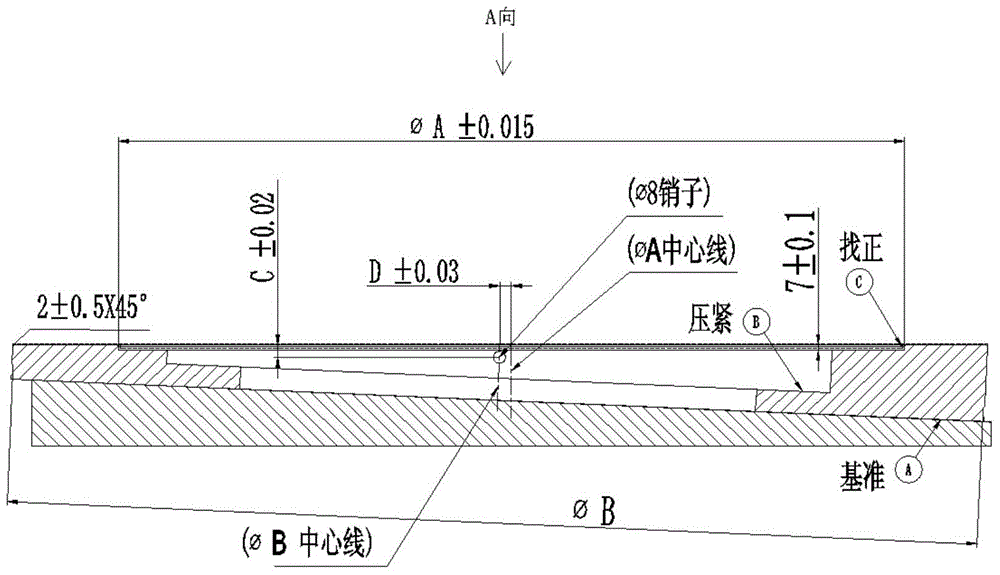

Image

  • A non-orthogonal structure casing processing method and fixture
  • A non-orthogonal structure casing processing method and fixture
  • A non-orthogonal structure casing processing method and fixture

Examples


Embodiment Construction

[0022] The structure of the present invention is as figure 2 As shown, it includes the bottom angle plate 6, the base 1 is set on the angle plate 6, and the positioning ring 2 is set on the base 1, and the positioning ring 2 is fixed on the base 1 by using a pressure plate and bolts 4; Pressing plate 2 3, pressing plate 2 is used to fix the outer bottom edge of the casing on the base; the positioning ring 2 matches the shape of the bottom of the casing 5, and the inclination angle between the upper surface of the base 1 and the horizontal plane is perpendicular to the center line of the casing The deflection angle between the directions is consistent; the base 1 can rotate relative to the angle plate 6, and a positioning pin is arranged between the base 1 and the angle plate 6; the positioning pin corresponds to the pin hole pre-set on the angle plate, and the pin hole The position of the machine is calculated and set according to the shape of the part to ensure the technical...


PUM


Abstract

The invention discloses a non-orthogonal structure cartridge receiver machining method and a clamp. The clamp comprises an angle plate on the bottommost layer, a base is arranged on the angle plate and provided with a positioning ring, and the positioning ring is fixed to the base through a pressing plate and a bolt; a second pressing plate is arranged on the outer side of the positioning ring and used for fixing the edge of the bottom of the outer side of a cartridge receiver to the base; the positioning ring is matched with the bottom end of the cartridge receiver in shape, and the inclining angle of the upper surface of the base coincides with the deflection angle between the center line of the cartridge receiver and the vertical direction; and the base can rotate relative to the angle plate, and a positioning pin is arranged between the base and the angle plate. The non-orthogonal structure cartridge receiver machining method and the clamp have the beneficial effects that according to the technical scheme, the non-orthogonal structure clamp is combined with a milling and turning composite machining method, the problem that installing and positioning during milling and turning composite machining process of a non-orthogonal structure cartridge receiver part are difficult is solved, the process route is shortened, secondary clamping errors are eliminated, the machining quality of the cartridge receiver is guaranteed, the machining efficiency is improved, and the non-orthogonal structure cartridge receiver machining method and the clamp have a good application prospect.

Description

technical field [0001] The invention relates to the technical field of aviation processing, in particular to a casing processing method and a fixture. Background technique [0002] The shape of the non-orthogonal structure casing is as follows: figure 1 As shown, it is an important load-bearing part of the aero-engine. The non-orthogonal structure casing parts have a special structure. Positioning, clamping and alignment are difficult, and the process route is different from conventional processing methods. It is difficult to guarantee the processing quality of this type of casing with conventional processing methods. Contents of the invention [0003] In order to solve the above-mentioned technical problems, the purpose of the present invention is to provide a processing method and a clamp for a casing, and the specific technical solutions are as follows: [0004] A non-orthogonal structure casing processing method is characterized in that it includes the following step...

Claims


Application Information

Patent Timeline
Patent Type & Authority Patents(China)
IPC IPC(8): B23P23/02B23Q3/06
CPCB23P23/02B23Q3/06
Inventor 赵明刘德生王海波唐秀梅李海泳
Owner SHENYANG LIMING AERO-ENGINE GROUP CORPORATION
Learn More