Air and hydraulic pressure system with power-controlled unmanned aerial vehicle launcher

A launching device and power control technology, which is applied in the field of aeronautical engineering, can solve problems such as ineffective integration, complex system structure, and slow dynamic response, and achieve the effects of enhanced dynamic response, simple mechanical structure, and effective integration

Active Publication Date:
View PDF6 Cites 4 Cited by
  • Summary
  • Abstract
  • Description
  • Claims
  • Application Information

AI Technical Summary

Problems solved by technology

[0004] The current gas-hydraulic system for the power control of the UAV launching device mostly uses hydraulic actuators and pulley speed-up as the power mechanism, which has a complex structure and slow dynamic response; Dynamic processes such as ejection, sliding car buffering, and sliding car reset use multiple hydraulic circuits, and the system structure is too complicated to be effectively integrated

Method used


Image

  • Air and hydraulic pressure system with power-controlled unmanned aerial vehicle launcher
  • Air and hydraulic pressure system with power-controlled unmanned aerial vehicle launcher
  • Air and hydraulic pressure system with power-controlled unmanned aerial vehicle launcher

Examples


Embodiment Construction

[0025] In order to make the object, technical solution and advantages of the present invention clearer, the present invention will be further described in detail below in conjunction with the accompanying drawings and embodiments. It should be understood that the specific embodiments described here are only used to explain the present invention, not to limit the present invention.

[0026] On the contrary, the invention covers any alternatives, modifications, equivalent methods and schemes within the spirit and scope of the invention as defined by the claims. Further, in order to make the public have a better understanding of the present invention, some specific details are described in detail in the detailed description of the present invention below. The present invention can be fully understood by those skilled in the art without the description of these detailed parts.

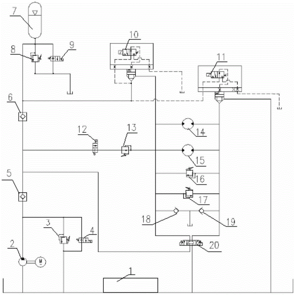
[0027] Such as figure 1 As shown, it is a gas-hydraulic system diagram of the power control of the UA...


PUM


Abstract

The invention belongs to the technical field of aeronautical engineering, and particularly relates to an air and hydraulic pressure system with a power-controlled unmanned aerial vehicle launcher. The air and hydraulic pressure system comprises an oil tank, a hydraulic pump, a one-way valve assembly, an energy accumulator and a motor assembly, all of which are sequentially connected. The motor assembly is connected back to the oil tank, and a loop is formed. According to the air and hydraulic pressure system, the dynamic responsiveness of a launching device is increased through a direct drive roller structural form, and the beneficial effects of being sufficient in power and high in speed are achieved. Compared with current unmanned aerial vehicle air and hydraulic pressure launchers, no pulley speed increase system is adopted, so that the mechanical structure of the launcher is simple. Meanwhile, the single hydraulic loop is adopted in the air and hydraulic pressure system, redundant design is carried out on key control elements, effective integration of the air and hydraulic pressure system is achieved, and the reliability of the air and hydraulic pressure system is improved.

Description

technical field [0001] The invention belongs to the technical field of aeronautical engineering, and in particular relates to a gas-hydraulic system for power control of an unmanned aerial vehicle launching device. Background technique [0002] With the continuous development of science and technology and the needs of national defense, the application of drones is becoming more and more extensive. UAV is one of the current high-tech weapons and equipment, which is widely used in military operations such as reconnaissance and strike. At present, the launch of UAVs in my country includes rocket-assisted launch, vehicle launch, autonomous take-off and landing, and elastic ejection. These types of launch are greatly affected by environmental factors, and some launch methods are difficult to maintain. For example, rocket boosting involves the maintenance of pyrotechnics, vehicle launch and autonomous take-off and landing require a long runway, and elastic elastics are prone to ...

Claims


Application Information

Patent Timeline
Patent Type & Authority Applications(China)
IPC IPC(8): B64F1/06F15B1/02F15B11/16
Inventor 余敏马祥森胡琦杨东伟韩世东郭茜
Why Eureka
Try Eureka