Pneumatic quick stacker crane for container

A pneumatic, container technology, applied in the stacking of objects, de-stacking, transportation and packaging of objects, etc., can solve the problems of unsatisfactory stacking speed and complex structure of the stacker, so as to shorten the packing time and structure. The effect of simplicity and simplification

Inactive Publication Date: 2016-02-24
河南小大机器人股份公司
View PDF8 Cites 6 Cited by
  • Summary
  • Abstract
  • Description
  • Claims
  • Application Information

AI Technical Summary

Problems solved by technology

[0003] The purpose of the present invention is to propose a pneumatic fast container palletizer for the problems of complex structure and unsatisfactory palletizing speed of the palletizer used inside the existing container

Method used


Image

  • Pneumatic quick stacker crane for container
  • Pneumatic quick stacker crane for container
  • Pneumatic quick stacker crane for container

Examples


Embodiment Construction

[0021] The present invention will be further described below in conjunction with accompanying drawing.

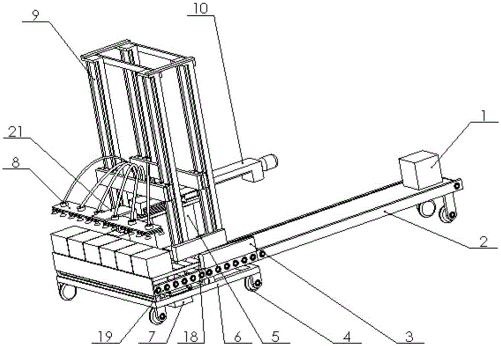
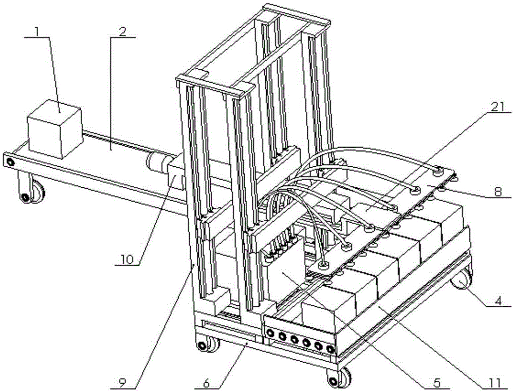
[0022] see figure 1 and 2 , container pneumatic fast palletizer, including frame drive mechanism, PLC controller 5, frame 6, horizontal pushing box mechanism 7, suction cup mechanism 8, lifting mechanism 9, longitudinal pushing mechanism 10 and conveyor belt mechanism 18; lifting mechanism 9 includes four screw guide rail slides 12; the guide rails of the four screw guide rail slides 12 are all fixed to the vehicle frame 6; the front part of the vehicle frame 6 is provided with a roller platform 19, and the driving parts of the horizontal push box mechanism 7 are arranged on the roller platform 19 bottoms, the horizontal push plate 20 is arranged on the top of the roller platform 19 and is driven by the driving parts; the conveyor belt mechanism 18 is arranged on the side of the vehicle frame 6; Push the packing boxes 1 to be placed in a row on the roller platform 19; the...


PUM


Abstract

The invention discloses a pneumatic quick stacker crane for a container. An existing stacker crane is complex in structure and low in stacking efficiency. A roller platform is arranged at a front portion of a frame of the pneumatic quick stacker crane; a transverse box pushing mechanism transversely pushes packaging boxes conveyed by a conveyor belt mechanism on the roller platform; a longitudinal pushing mechanism comprises a lead rod guide rail sliding table, a longitudinal push plate, and two equal-height sliding plates arranged with a distance therebetween; the two ends of each sliding plate are fixed with sliding tables of two lead screw guide rail sliding tables of an elevator mechanism; a guide rail of the lead rod guide rail sliding table of the longitudinal pushing mechanism is fixed with the two sliding plates; the longitudinal push plate is fixed with a sliding table of the lead rod guide rail sliding table of the longitudinal pushing mechanism and a sucker mechanism; a lead screw of the lead rod guide rail sliding table of the longitudinal pushing mechanism is driven by a servo motor. The conveyor belt mechanism and the transverse box pushing mechanism of the pneumatic quick stacker crane for the container are capable of continuously conveying the packaging boxes to the roller platform, thereby improving the box conveying efficiency; after the packaging boxes are gathered into a row, all the packaging boxes are sucked up by the sucker mechanism and once conveyed into the container by the longitudinal pushing mechanism, and therefore, a stacking speed is increased.

Description

technical field [0001] The invention belongs to the field of transportation equipment and relates to a palletizer, in particular to a pneumatic fast palletizer for containers. Background technique [0002] At present, most palletizers are mainly used in occasions where the space position is not limited. The utility model patent with the patent number of 200920227870.7 discloses a palletizer used inside the container, which can transport the user's container from the end of the production line or the warehouse to the container and stack it neatly. The problem with this palletizer is: the structure is relatively Complexity, high manufacturing cost, and unsatisfactory palletizing speed. Contents of the invention [0003] The object of the present invention is to propose a pneumatic fast container palletizer for the problems of complex structure and unsatisfactory palletizing speed of the palletizer used inside the existing container. [0004] Concrete scheme of the present ...

Claims


Application Information

Patent Timeline
Patent Type & Authority Applications(China)
IPC IPC(8): B65G61/00
CPCB65G61/00
Inventor 孟永江方超
Owner 河南小大机器人股份公司
Why Eureka
Try Eureka