Gas well under-pressure induced-flow plug-removal draining technique

A technology of induced blowout and gas well, applied in the direction of wellbore/well parts, earthwork drilling and production, etc., can solve the problems that cannot be realized with pressure swabbing, induce blowout, unplug and discharge liquid, etc., to fill the technological gap, safe and reliable process technology , the effect of reducing operational risk

Inactive Publication Date: 2016-02-24
LIAOHE GASOLINEEUM EXPLORATION BUREAU
View PDF7 Cites 5 Cited by
  • Summary
  • Abstract
  • Description
  • Claims
  • Application Information

AI Technical Summary

Problems solved by technology

It overcomes the inability of existing gas wells to achieve pressure swabbing to induce eruption, blockage removal, and liquid discharge

Method used


Image

  • Gas well under-pressure induced-flow plug-removal draining technique
  • Gas well under-pressure induced-flow plug-removal draining technique

Examples


Embodiment Construction

[0064] A gas well pressure-induced blowout removal plugging removal process, the process steps are as follows:

[0065] 1. Construction steps of pumping and drainage under pressure:

[0066] Ⅰ Installation equipment

[0067] ① On-site layout, vehicle swinging, and derrick;

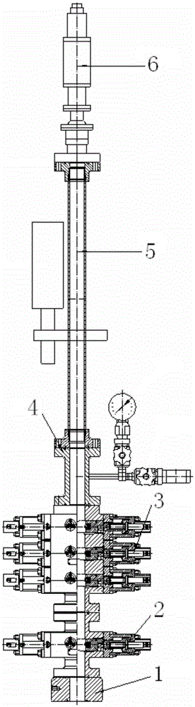
[0068] ② Ground connection wellhead blowout preventer: reducing flange 1, hydraulic single ram blowout preventer 2, hydraulic three ram blowout preventer 3, pressure relief tee 4, blowout preventer 5 connected in sequence, hydraulic The single ram BOP 2 and the hydraulic three ram BOP 3 form a BOP group, and the hydraulic three ram BOP 3 consists of a shear ram BOP, a fully sealed ram BOP and a semi-hydraulic three ram BOP The composition of the ram blowout preventer, such as figure 1 shown;

[0069] ③Install and inspect the wire rope sealer 6, the rope cap, and install the wellhead construction console;

[0070] ④ Remove the threaded flange on the upper part of the original gas production tree, install...


PUM


Abstract

The present invention relates to the technical field of gas production of gas wells, and especially relates to a gas well under-pressure induced-flow plug-removal draining technique. The technique comprises an under-pressure swabbing drainage construction procedure which comprises equipment installation. The equipment installation comprises site layout, vehicle arrangement and derrick erection; and connection of wellhead blowout preventers on the ground, an adapter flange, a hydraulic-drive single-ram blowout preventer, a hydraulic-drive three-ram blowout preventer, a pressure release tee joint and a blowout preventing pipe being connected in turn, the hydraulic-drive single-ram blowout preventer and the hydraulic-drive three-ram blowout preventer forming a blowout preventer group, and the hydraulic-drive three-ram blowout preventer being composed of a shear ram preventer, a blind ram preventer and a semi-sealed ram preventer. The swabbing draining technology and the under-pressure operation technology are organically combined, long-range control and operation of wellhead pressure during under-pressure swabbing operation is realized, operating risks are lowered, the technique is safe and reliable, requirements for gas well under-pressure swabbing draining construction operation are met, and technical blanks in national gas well under-pressure swabbing induced-flow plug-removal draining techniques are filled.

Description

Technical field: [0001] The invention relates to the technical field of gas well production, in particular to a gas well pressure-induced blowout removal, blockage removal and fluid drainage process. Background technique: [0002] During the gas production process of gas wells, the gas layer will be flooded and blocked due to fluid accumulation in the well, resulting in a gradual decrease in production capacity, or even in a state of intermittent or shutdown, which seriously affects the production of gas wells. At present, the methods commonly used in gas wells, including production induction, plugging removal and pressure drainage, mainly include coiled tubing, gas lift drainage, etc. The construction period is long, the cost is high, and sometimes the effect is not obvious. It is the most economical and effective method for gas wells to use the production string to induce blowout to remove plugging and discharge liquid. [0003] At present, the swabbing liquid drainage te...

Claims


Application Information

Patent Timeline
Patent Type & Authority Applications(China)
IPC IPC(8): E21B31/03
CPCE21B31/03
Inventor 原学玉徐宪胜于开斌刘付喜薛文礼魏后超王子磊郑嵇元郭礼关培元葛继伟王元
Owner LIAOHE GASOLINEEUM EXPLORATION BUREAU
Why Eureka
Try Eureka