Circulating air intake system

A technology of air intake system and air passage, which is applied in the direction of charging system, exhaust gas recirculation, machine/engine, etc.

Active Publication Date: 2016-02-24
康跃科技(山东)有限公司
View PDF7 Cites 4 Cited by
  • Summary
  • Abstract
  • Description
  • Claims
  • Application Information

AI Technical Summary

Problems solved by technology

[0008] In view of this, the object of the present invention is to provide a circulating intake system for the engine, the structural design of the circula

Method used


Image

  • Circulating air intake system
  • Circulating air intake system
  • Circulating air intake system

Examples


Embodiment Construction

[0027] The embodiment of the invention discloses a circulating air intake system for an engine, so as to solve the problems that the exhaust gas circulation system in the existing engine works normally under different working conditions.

[0028] The following will clearly and completely describe the technical solutions in the embodiments of the present invention with reference to the accompanying drawings in the embodiments of the present invention. Obviously, the described embodiments are only some, not all, embodiments of the present invention. Based on the embodiments of the present invention, all other embodiments obtained by persons of ordinary skill in the art without making creative efforts belong to the protection scope of the present invention.

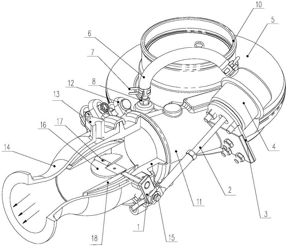
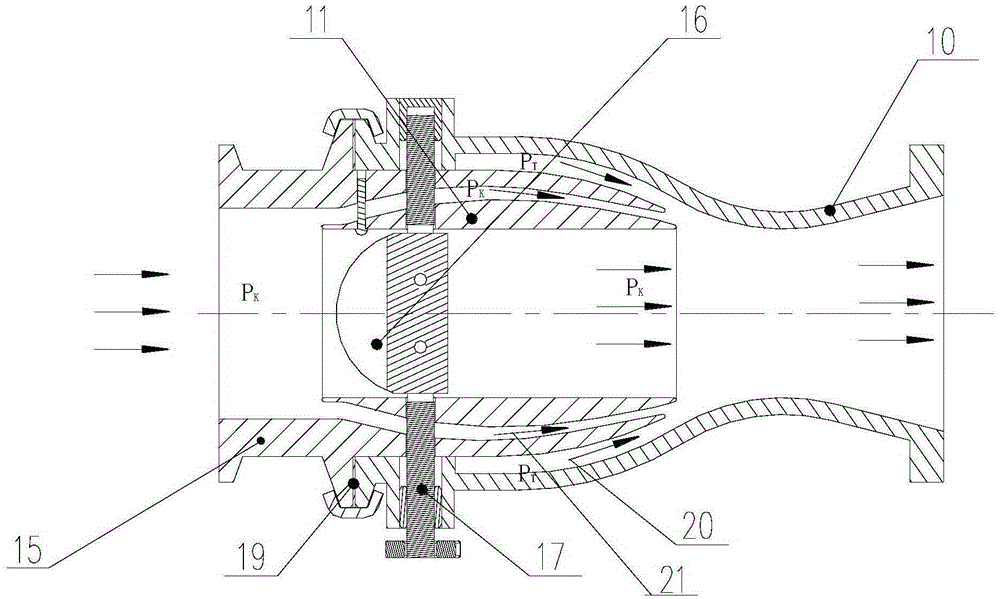
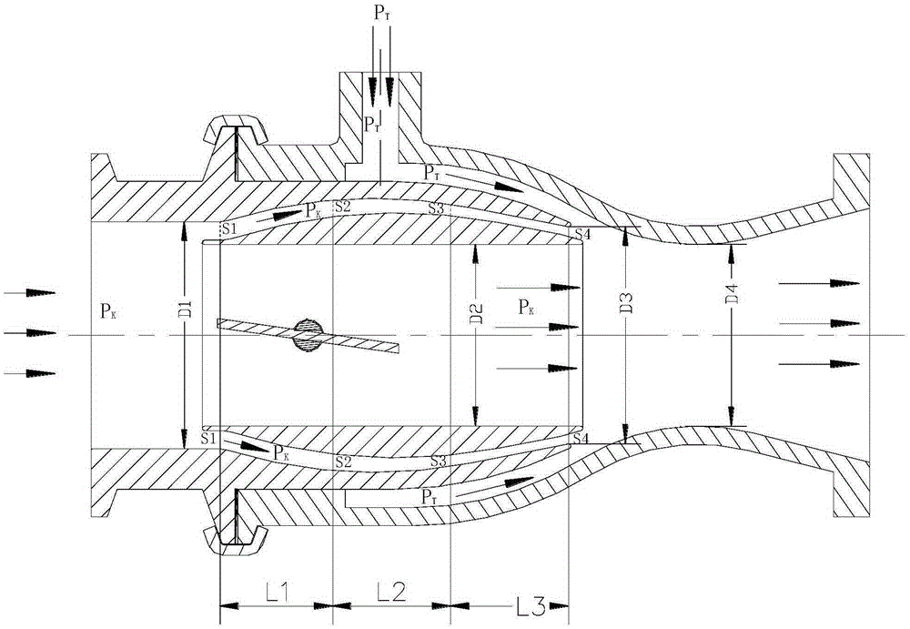
[0029] see Figure 1-Figure 3 , figure 1 Schematic diagram of the structure of the circulating air intake system provided by the embodiment of the present invention; figure 2 A schematic cross-sectional structural schemat...


PUM


Abstract

The invention discloses a circulating air intake system for an engine. The circulating air intake system comprises a turbocharger compressor casing and an EGR mixer; the EGR mixer comprises a mixer outer shell, and an external air duct and a circulating exhaust gas duct in the mixer outer shell; the circulating air intake system further comprises a regulating valve for regulating a diameter of the external air duct; the regulating valve is arranged within the mixer outer shell and mechanically connected with a control executor; the control executor comprises an execution response device and an air control device of which one end communicates with the turbocharger compressor casing. A pressure of external incoming air in the turbocharger compressor casing is sensed through the air control device; the air control device originates a control action and a mechanical motion is generated through the execution response device; and the motion is transmitted to the regulating valve to regulate an external air pressure in the external air duct, so that a difference between the external air pressure and a pressure of circulating exhaust gas going into the mixer outer shell is kept within an ideal value, and therefore, an exhaust gas circulating system of the engine is kept efficient in working under different working conditions.

Description

technical field [0001] The invention relates to the technical field of the automobile industry, and more specifically relates to a circulating air intake system for an engine. Background technique [0002] As China's emission regulations become increasingly stringent, engines, especially diesel engines, must greatly reduce the emission of NOx, the main emission. At present, EGR technology is one of the effective means to reduce NOx emission of diesel engine recognized internationally. EGR is more and more applied to the engine. The full name of EGR is ExhaustGasRecirculation, which means that part of the exhaust gas discharged from the engine is returned to the intake manifold, and mixed with fresh air to enter the cylinder again, thereby reducing the generation of NOx. [0003] NOx is a gas that is extremely harmful to the human body. It is mainly produced under the condition of high temperature and rich oxygen. The higher the combustion temperature and oxygen concentratio...

Claims


Application Information

Patent Timeline
IPC IPC(8): F02M26/10F02M26/19
Inventor 王航张扬军桑悟海袁道军信效芬郭朋亮韩霏
Owner 康跃科技(山东)有限公司
Why Eureka
Try Eureka