
A fan device and electronic equipment

A fan and centrifugal fan technology, applied in the mechanical field, can solve the problem of high noise of the centrifugal fan device, and achieve the effect of reducing noise and reducing noise

Active Publication Date: 2020-01-31
LENOVO (BEIJING) LTD
View PDF5 Cites 0 Cited by
  • Summary
  • Abstract
  • Description
  • Claims
  • Application Information

AI Technical Summary

Problems solved by technology

[0006] The embodiment of the present application solves the technical problem of high noise in the centrifugal fan device in the prior art by providing a fan device and electronic equipment, and achieves the technical effect of reducing the noise in the centrifugal fan device

Method used


Image

  • A fan device and electronic equipment
  • A fan device and electronic equipment
  • A fan device and electronic equipment

Examples


Embodiment 1

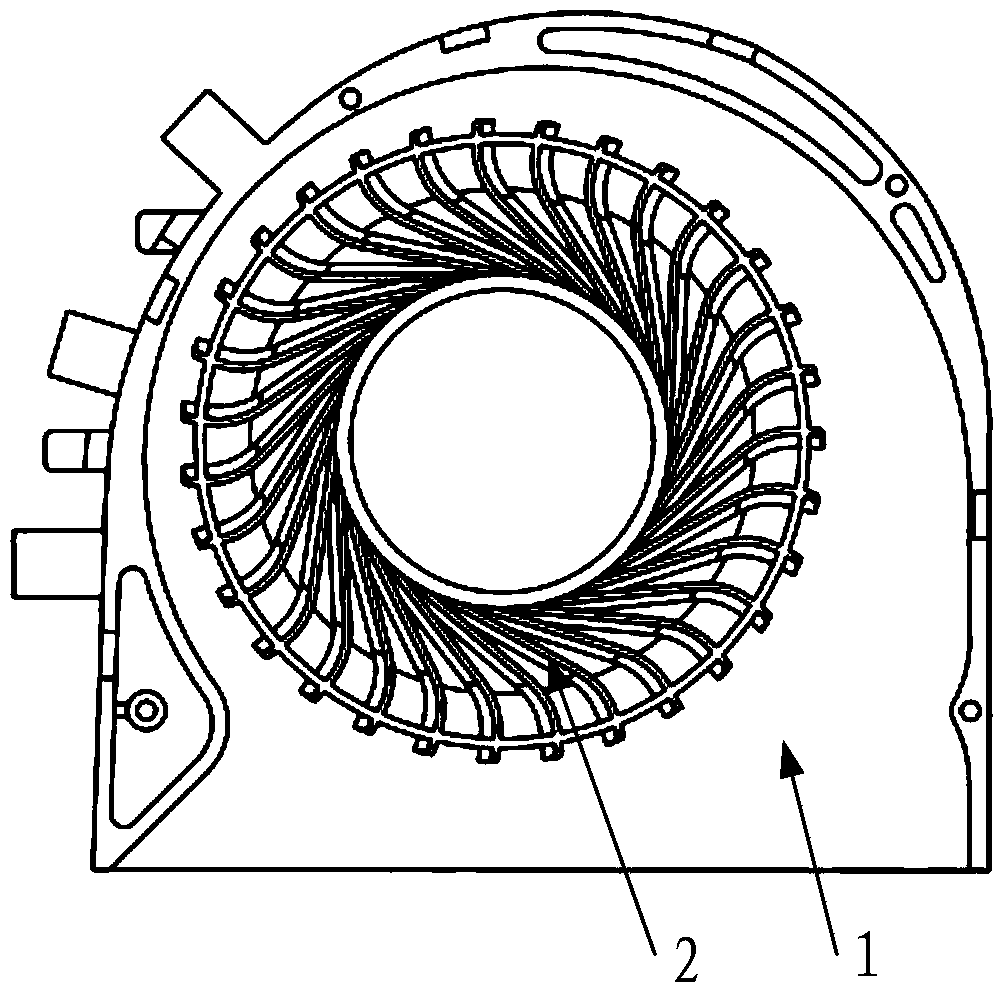
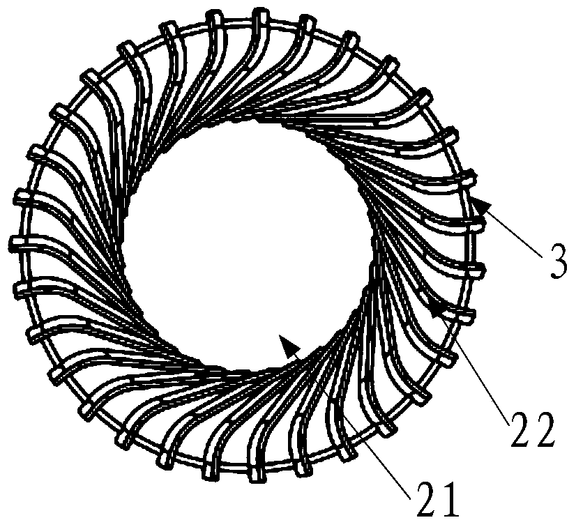
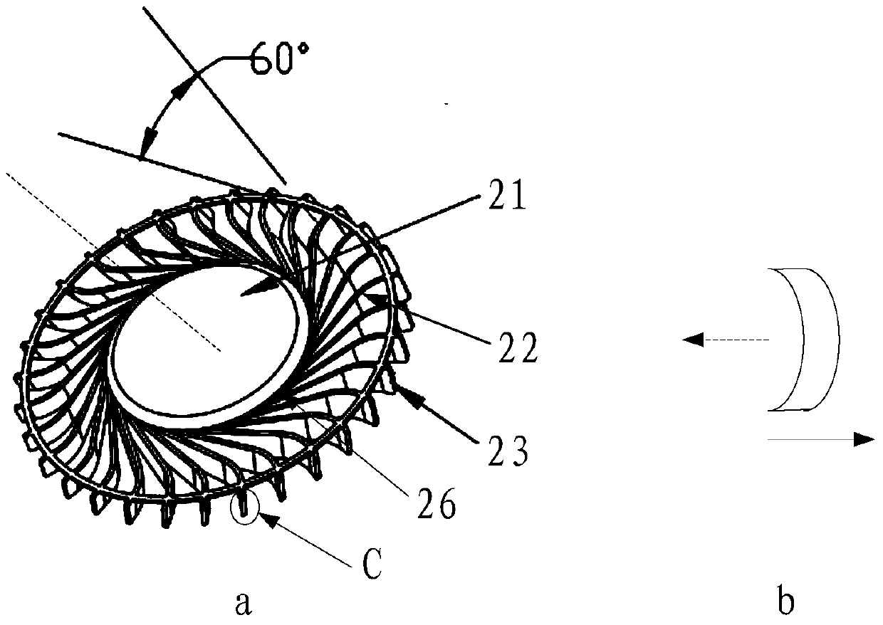
[0058] Please refer to figure 1 , a fan device provided for this application, including: a volute 1 and an impeller 2, the impeller 2 is arranged in the volute, in practical applications, the impeller 2 can be fixed in the volute 1 by bolts and threads, of course, Can also pass other ways, do not limit here, also be provided with air inlet and air outlet (not shown in the figure) on the volute 1, so that air flow can enter fan device from the air inlet on volute 1, and from volute The air outlet on the shell 1 flows out of the fan unit. Please refer to figure 2 , is a structural schematic diagram of the impeller 2 in the fan device. The impeller 2 includes a hub 21 and fan blades 22. The hub 21 has a rotating axis (not shown in the figure), which is perpendicular to the plane where the hub 21 is located. In practical applications Among them, the hub 21 can rotate around the axis, and the number of fan blades 22 is at least two. In this embodiment, the number of fan blades 2...

Embodiment 2

[0072] Based on the same inventive concept as the first embodiment of the present application, the second embodiment of the present application also provides an electronic device, including:

[0073] A device body, where at least one electronic component is arranged in the device body;

[0074] A fan device is arranged inside the main body of the device for dissipating heat generated by the at least one electronic component, and the fan device includes:

[0075] volute;

[0076] an impeller, the impeller is arranged in the volute;

[0077] The impeller includes a hub and at least two fan blades;

[0078] Wherein, the hub has an axis, and the volute is provided with an air inlet and an air outlet, the airflow can enter the air inlet along the axial direction of the impeller, and can flow out of the air outlet along the radial direction of the impeller. export wind;

[0079] The at least two fan blades are arranged on the hub, wherein the axial track of each of the at least ...


PUM


Abstract

The invention discloses a fan device and an electronic device. The fan device comprises a volute and a vane wheel, wherein the vane wheel is arranged inside the volute, and comprises a hub and at least two fan blades; the hub has an axis; air inlets and air outlets are formed in the volute; airflow can enter the air inlets in the axial direction of the vane wheel, and can flow out of the air outlets in the radial direction of the vane wheel; the at least two fan blades are arranged on the hub; and the included angle formed by the axial path line of each fan blade in the at least two fan blades in the axial direction and a radial plane vertical to the axis is an acute angle.

Description

technical field [0001] The invention relates to the field of mechanical technology, in particular to a fan device and electronic equipment. Background technique [0002] With the continuous development of science and technology, electronic products have also been developed rapidly. In order to avoid damage to internal components caused by the heat generated by electronic products during work, fans are usually installed inside electronic products to promote the internal cooling of the casing. The heat is dissipated to the outside. [0003] In many electronic devices, a centrifugal fan is used, which includes: a volute; an impeller, the impeller is arranged in the volute; the impeller includes a hub, and at least two fan blades. The volute is provided with an air inlet and an air outlet, the air flow enters the air inlet along the axial direction of the impeller, and flows out of the outlet air along the radial direction of the impeller. [0004] However, in the process of r...

Claims


Application Information

Patent Timeline
Patent Type & Authority Patents(China)
IPC IPC(8): F04D17/16F04D29/28F04D29/30F04D29/66F04D29/42H05K7/20
Inventor 贾自周顾荣华郭联明
Owner LENOVO (BEIJING) LTD
Learn More