
Sterilization ventilator capable of achieving remote control and online monitoring

A remote control, ventilator technology, applied in ventilation systems, space heating and ventilation, space heating and ventilation details, etc., can solve the problems of inconvenient remote operation and real-time online monitoring, inability to kill, and difficulty in concentrating , to achieve the effect of convenient remote operation and real-time monitoring, simple and convenient operation, and various functions

Active Publication Date: 2016-02-24
CHONGQING GREEN AKIRA TECH DEV
View PDF6 Cites 6 Cited by
  • Summary
  • Abstract
  • Description
  • Claims
  • Application Information

AI Technical Summary

Problems solved by technology

[0002] At present, some buildings have begun to use natural ventilators. Natural ventilators are installed on doors, windows or glass curtain walls. The recycling of dirty air causes indoor personnel to have headaches, dizziness, nausea, difficulty concentrating, dry cough, dry and itchy skin and other pathogenic building syndromes
However, since this natural ventilator has no power to supply air, when the indoor and outdoor air pressure difference or wind pressure difference is small, the air circulation power is insufficient to deliver fresh air to the room, and ordinary natural ventilators can only filter large particles and Mosquitoes can only filter the air to a certain extent, but cannot kill pathogenic bacteria and viruses such as influenza virus and Staphylococcus aureus in the air
In addition, the existing ventilators do not have the functions of remote control and online monitoring, which is not convenient for remote operation and real-time online monitoring

Method used


Image

  • Sterilization ventilator capable of achieving remote control and online monitoring
  • Sterilization ventilator capable of achieving remote control and online monitoring

Examples


Embodiment Construction

[0013] The following will clearly and completely describe the technical solutions in the embodiments of the present invention with reference to the accompanying drawings in the embodiments of the present invention. Obviously, the described embodiments are only some, not all, embodiments of the present invention. Based on the embodiments of the present invention, all other embodiments obtained by persons of ordinary skill in the art without creative efforts fall within the protection scope of the present invention.

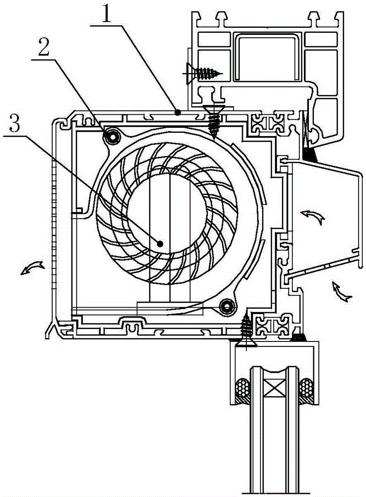
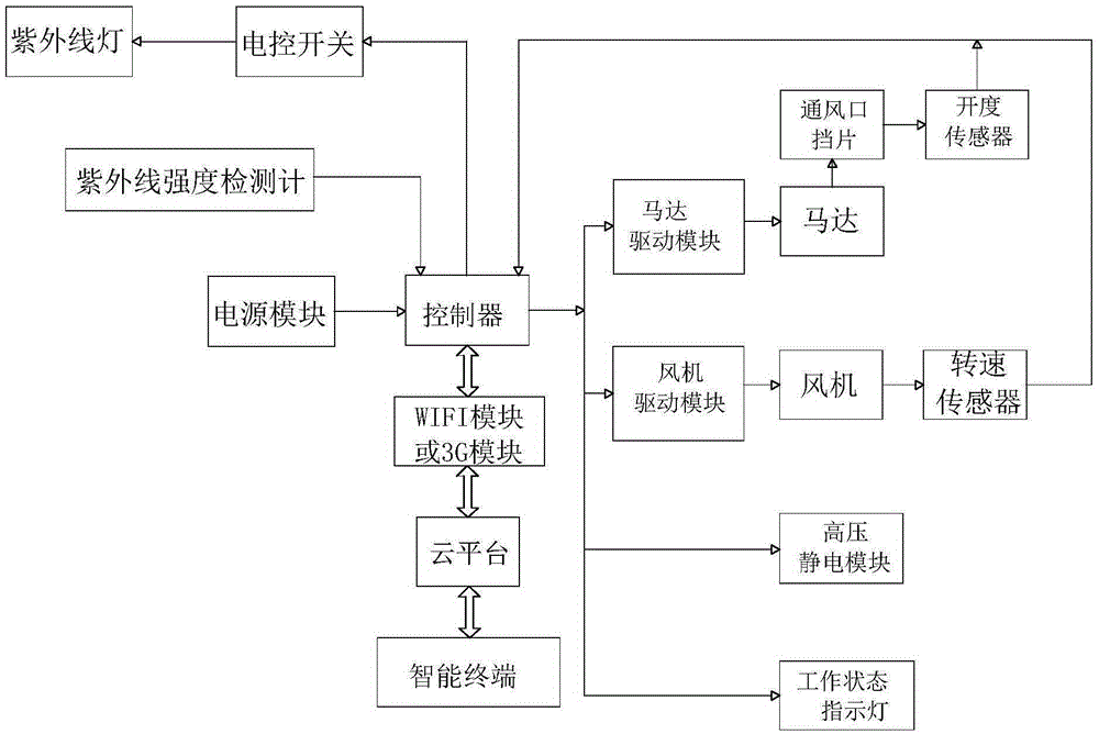
[0014] see figure 1 , figure 2 , a sterilizing ventilator capable of remote control and on-line monitoring, comprising a housing 1 and a fan 2 arranged in the housing 1, a number of air purification components are installed in the housing 1, and an air intake chamber and an air intake chamber are arranged in the air purification components Fan 2 cavity, UV ultraviolet germicidal lamp 3 is installed in the air inlet cavity, fan 2 is installed in the fan 2 cavity, ...


PUM


Abstract

The invention provides a sterilization ventilator capable of achieving remote control and online monitoring. The sterilization ventilator comprises a shell and a draught fan arranged in the shell. A plurality of air purification assemblies are arranged in the shell. Gas inlet cavities and draught fan cavities are formed in the air purification assemblies. UV sterilization lamps are arranged in the gas inlet cavities. Draught fans are arranged in the draught fan cavities. The rotation central lines of the draught fans are parallel to the length direction of the shell. The gas inlets of the gas inlet cavities are opposite to air inlets. The gas outlets of the draught fans are opposite to air outlets. The sterilization ventilator further comprises a remote control and monitoring system used for remotely controlling and online monitoring the ventilator. The remote control and monitoring system comprises a controller connected with a power supply module. The controller is in communication with a remote control system and an online monitoring system. The controller is further connected with an ultraviolet intensity detector. The UV sterilization lamps are controlled through the controller and an electric control switch.

Description

technical field [0001] The invention relates to a building ventilation device, in particular to a sterilizing ventilator capable of remote control and online monitoring. Background technique [0002] At present, some buildings have begun to use natural ventilators. Natural ventilators are installed on doors, windows or glass curtain walls. The recycling of dirty air causes indoor personnel to have headaches, dizziness, nausea, difficulty concentrating, dry cough, dry and itchy skin and other pathogenic building syndromes. However, since this natural ventilator has no power to supply air, when the indoor and outdoor air pressure difference or wind pressure difference is small, the air circulation power is insufficient to deliver fresh air to the room, and ordinary natural ventilators can only filter large particles and Mosquitoes can only filter the air to a certain extent, but cannot kill pathogenic bacteria and viruses such as influenza virus and Staphylococcus aureus in t...

Claims


Application Information

Patent Timeline
Patent Type & Authority Applications(China)
IPC IPC(8): F24F7/007F24F11/02F24F13/00
CPCF24F3/16F24F7/007F24F11/30F24F11/58F24F11/62F24F11/89F24F2110/00F24F2140/40F24F8/192F24F8/20
Inventor 韦科宇张建平
Owner CHONGQING GREEN AKIRA TECH DEV
Learn More