Single-probe three-coil maglev train gap sensor with fault location function

A gap sensor and fault location technology, applied in the direction of instruments, using electromagnetic means, measuring devices, etc., can solve the problems of inability to install, reduce magnetic field interference, and different signal source frequencies, etc., to facilitate installation, reduce the size of the probe, and reduce costs Effect

Inactive Publication Date: 2016-02-24
SOUTHWEST JIAOTONG UNIV
View PDF4 Cites 4 Cited by
  • Summary
  • Abstract
  • Description
  • Claims
  • Application Information

AI Technical Summary

Problems solved by technology

Another double-probe air-gap sensor generally uses a double-coil detection method to realize the self-diagnosis function. Each probe contains a detection coil. In order to avoid the magnetic field coupling between the two probe coils, the two probe coils are generally Arranged at a far distance, and the two probe coils generally use signal sources of different frequencies, and when a fault occurs in the detection channels of the two coils, it is impossible to distinguish which fault occurs, and the fault cannot be located
[0004] The main deficiency of the current technology is that there is only one detection result when a single coil is detected in a single probe. The sensor itself has no diagnostic function, and the suspension controller cannot judge whether the detection result of the sensor is correct. When the sensor itself fails, it will directly cause the suspension control system to fail; In order to reduc

Method used


Image

  • Single-probe three-coil maglev train gap sensor with fault location function
  • Single-probe three-coil maglev train gap sensor with fault location function
  • Single-probe three-coil maglev train gap sensor with fault location function

Examples


Embodiment Construction

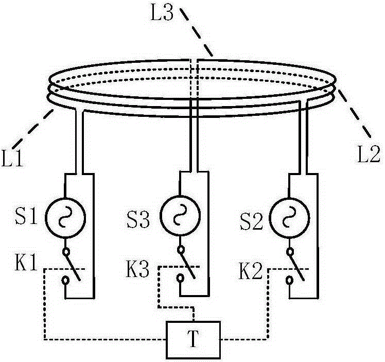
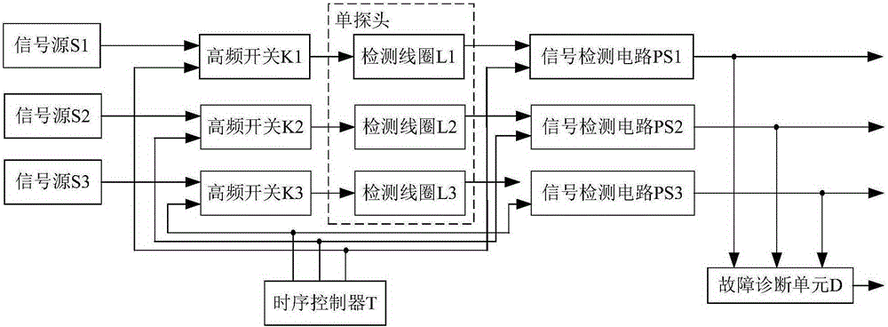
[0019] figure 1 and figure 2 As shown, a specific embodiment of the present invention is: comprising a controllable high-frequency switch connected to the high-frequency signal source on the vehicle body, a probe coil connected to the controllable high-frequency switch, a signal detection circuit connected to the probe coil, A self-diagnosis unit connected to the signal detection circuit; characterized in that the sensor is composed of a single probe, and there are 3 detection coils (L1, L2 and L3) in the probe; the size and winding of the 3 detection coils (L1, L2 and L3) The same direction, and completely overlapped in space; the input terminals of the three detection coils (L1, L2 and L3) are respectively connected to the three high-frequency signal sources (S1, S2) through three controllable high-frequency switches (K1, K2 and K3) and S3); the output terminals of the three detection coils (L1, L2 and L3) are respectively connected to the independent signal detection circ...


PUM


Abstract

A single-probe three-coil maglev train gap sensor with a fault location function comprises controllable high-frequency switches which are each connected with a high-frequency signal source on a train body, probe coils which are each connected with one controllable high-frequency switch, signal detection circuits which are each connected with one probe coil, and a self-diagnosis unit connected with the signal detection circuits. The input ends of the three detection coils inside sensor probes are respectively connected with the three high-frequency signal sources through the three controllable high-frequency switches; the output ends of the three detection coils are respectively connected with the signal detection circuits which are independent of one another; the controllable high-frequency switches and the signal detection circuits are connected with a timing controller (T); and the three signal detection circuits output three independent air gap detection values. When there is a single-channel detection fault, the fault diagnosis unit outputs fault location information and indicates the position of a detection channel where the fault occurs. When a single channel fails, an effective real air gap value can still be provided. The single-probe three-coil maglev train gap sensor has a redundancy function.

Description

technical field [0001] The invention relates to a gap sensor with a fault location function, in particular to a non-contact sensor for the suspension gap of a maglev train. Background technique [0002] The maglev train adjusts the current in the suspension electromagnet through the suspension control system to keep the train in stable suspension. The suspension air gap sensor can realize non-contact real-time detection of the suspension air gap between the train electromagnet and the track, and at the same time send it to the suspension controller for closed-loop control . Therefore, the accuracy and reliability of the air gap sensor directly affect the performance of the suspension control system. Any abnormal output of the air gap sensor will affect the dynamic performance of the train suspension control system, reduce the ride comfort of the train, and even aggravate the train-rail coupling. Vibration causes the control system to collapse and endangers the safety of tra...

Claims


Application Information

Patent Timeline
IPC IPC(8): G01B7/14G01R35/00
Inventor 靖永志张昆仑董金文刘国清王滢郭小舟廖海军何飞
Owner SOUTHWEST JIAOTONG UNIV
Why Eureka
Try Eureka