
Operation amplifier gain measurement circuit

A technology for measuring circuits and operational amplifiers, applied in the field of operational amplifiers, which can solve the problems of difficult and accurate measurement of high-gain operational amplifiers, and achieve the effect of ensuring stability

Inactive Publication Date: 2016-02-24
WUXI BIXUN TECH
View PDF6 Cites 4 Cited by
  • Summary
  • Abstract
  • Description
  • Claims
  • Application Information

AI Technical Summary

Problems solved by technology

However, due to pickup, stray current, or thermocouple effects that may generate very small voltages at the input of the op amp, errors will be difficult to avoid, so high-gain op amps are difficult to measure accurately

Method used


Image

  • Operation amplifier gain measurement circuit
  • Operation amplifier gain measurement circuit
  • Operation amplifier gain measurement circuit

Examples


Embodiment Construction

[0011] The specific embodiments of the present invention will be further described below in conjunction with the accompanying drawings.

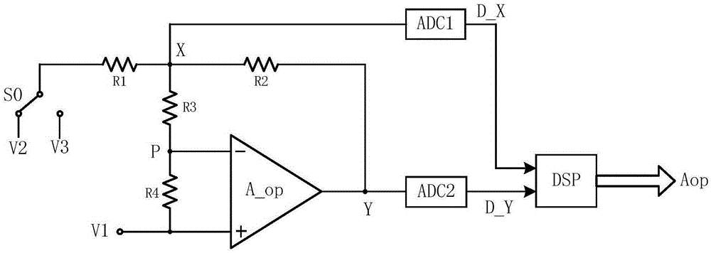
[0012] see figure 1 , The operational amplifier gain measurement circuit of the present invention is composed of operational amplifier A_op, analog-to-digital converters ADC1-ADC2, digital processing module DSP, switch S0 and resistors R1-R4.

[0013] The operational amplifier A_op is the operational amplifier to be tested itself or its copy; one end of the resistors R1, R2, R3, and the input end of the analog-to-digital converter ADC1 are connected to point X, and the other end of the resistor R2, the output end of the operational amplifier A_op, and the analog-to-digital converter ADC2 The input terminal is connected to point Y, the other end of resistor R3, one end of resistor R4, and the inverting input terminal of op amp A_op are connected to point P, the other end of resistor R4 and the non-inverting input end of op amp A_op are connec...


PUM


Abstract

The invention discloses an operation amplifier gain measurement circuit, comprising an operation amplifier, a first analog-to-digital converter, a second analog-to-digital converter, a second analog-to-digital converter, a digital processing module, a switch and a four resistors (from the first resistor to the fourth resistor); terminals of the resistors from the first resistor to the third resistor and the input terminal of the first analog-to-digital converter are commonly connected to an X point; the other terminal of the second resistor, the output terminal of the operation amplifier, and the input terminal of the second analog-to-digital converter are commonly connected to an Y point; the other terminals of the third resistor and the fourth resistor and the inverted input terminal of the operation amplifier are commonly connected to a P point; the other terminal of the fourth resistor and the input terminal of the operation amplifier are commonly connected to first voltage; the other terminal of the first resistor is connected to second voltage or third voltage through the switch; and the output terminals of the first analog-to-digital converter and the second analog-to-digital converter are connected to the input terminals of the digital processing module. The invention can accurately measures the practical gain of the operation amplifier and regulates the gain. In the high gain operation amplifier with a negative resistance unit, the invention can control the negative resistance value according to the practical gain so as to guarantee to achieve the target gain value under the condition that the operation amplifier is stable.

Description

technical field [0001] The invention belongs to the field of operational amplifiers and relates to an operational amplifier gain measurement circuit. Background technique [0002] High-gain operational amplifiers have a wide range of requirements in feedback systems. Taking high-precision pipelined analog-to-digital converters as an example, high-gain operational amplifiers in the pipeline stage are an important condition to ensure conversion accuracy, so their performance must be accurately measured. High-gain op amps are difficult to measure accurately, however, since pickup, stray current, or thermocouple effects may produce very small voltages at the op amp input, and errors will be unavoidable. Contents of the invention [0003] The invention provides an operational amplifier gain measuring circuit, the purpose of which is to accurately measure the actual gain of the operational amplifier. [0004] Technical scheme of the present invention is as follows: [0005] An...

Claims


Application Information

Patent Timeline
IPC IPC(8): G01R31/28
CPCG01R31/28
Inventor 丁洋任咏林
Owner WUXI BIXUN TECH
Learn More