Optical lens
An optical lens and optical length technology, applied in the field of optical lenses, can solve the problems of large overall field of view and short focal length of the lens, and achieve the effect of small field of view on the object side, good observation, and long focal length
- Summary
- Abstract
- Description
- Claims
- Application Information
AI Technical Summary
Problems solved by technology
Method used
Image

Examples
Embodiment 1
[0049] An optical lens, from the object side to the image side, sequentially includes a first lens L1 with a positive refractive power and a convex surface facing the object side, a meniscus-shaped second lens L2 with a convex surface facing the object side, and a biconcave third lens L3 , a fourth lens L4, a fifth lens L5, and a sixth lens L6 with positive refractive power.
[0050] Fifth lens L5 and sixth lens L6 are not necessarily required to have positive refractive power.
[0051] The first lens L1 satisfies the following formula:
[0052] 0.5≤F1 / F≤8.0
[0053] Wherein, F1 is the focal length value of the first lens L1, and F represents the focal length value of the entire group of optical lenses.
[0054] The first lens L1 has positive refractive power, can gather light from the object side, can effectively correct the aberration of the entire optical system, realize high pixel and small distortion of the optical lens, and lengthen the overall focal length of the lens...
Embodiment 2
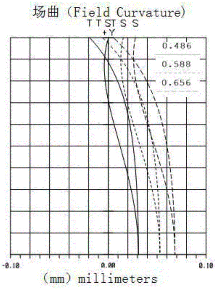
[0067] Figure 1a It is a structural schematic diagram of an optical lens provided in an embodiment of the present invention. The optical lens includes in order from the object side to the image side: a first lens L1, a second lens L2, an aperture element L7, a third lens L3, a fourth lens L4, a fifth lens L5, a sixth lens L6, a filter Color film IR, glass film CG and imaging surface IMA. Wherein, the first lens L1 is a lens with a positive refractive power and a convex surface facing the object side, the second lens L2 is a meniscus lens with a positive refractive power and a convex surface facing the object side, and the third lens L3 is A biconcave lens, the fourth lens L4 has a positive refractive power, the fifth lens L5 is a biconvex lens with a positive refractive power, the sixth lens L6 is a biconcave lens with a negative refractive power, and the fifth lens L5 and sixth lens L6 form a cemented lens.
[0068] The first lens L1 has a positive refractive power, can ga...
Embodiment 3
[0081] The main difference between the present embodiment and the second embodiment is that the selection of the lens material in the present embodiment is different, and the optical power of the second lens is different.
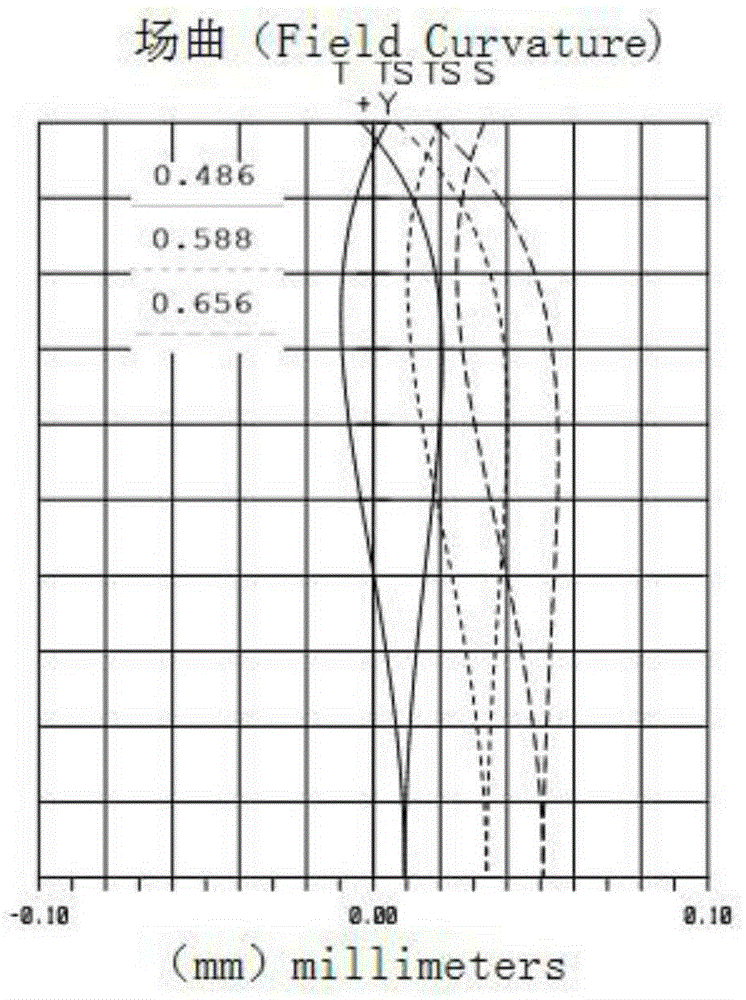
[0082] Such as Figure 2a As shown, an optical lens, from the object side to the image side, includes: a first lens L1, a second lens L2, an aperture element L7, a third lens L3, a fourth lens L4, a fifth lens L5, and a sixth lens L6, color filter IR, glass CG and imaging surface IMA. Wherein, the first lens L1 is a lens with a positive refractive power and a convex surface facing the object side, the second lens L2 is a meniscus lens with a negative refractive power and a convex surface facing the object side, and the third lens L3 It is a biconcave lens with negative refractive power, the fourth lens L4 has positive refractive power, the fifth lens L5 is a biconvex lens with positive refractive power, and the sixth lens L6 has negative refractive power ...
PUM
 Abstract
Description
Claims
Application Information