Antenna for generating radial spreading RF OAM wave beams based on annular travelling wave antenna

A traveling wave antenna and loop technology, applied in leaky waveguide antennas, waveguide horns, circuits, etc., can solve the problems of enlargement, difficulty in receiving at the receiving end, unfavorable orbital angular momentum beam multiplexing and long-distance propagation, etc. Use and speed up the effect of practical use

Active Publication Date: 2016-02-24
ZHEJIANG UNIV
View PDF3 Cites 12 Cited by
  • Summary
  • Abstract
  • Description
  • Claims
  • Application Information

AI Technical Summary

Problems solved by technology

The diameter of the radio frequency orbital angular momentum beam becomes significantly larger as the propagation distance increases, and there is a phase singularity in the center of the be

Method used


Image

  • Antenna for generating radial spreading RF OAM wave beams based on annular travelling wave antenna
  • Antenna for generating radial spreading RF OAM wave beams based on annular travelling wave antenna
  • Antenna for generating radial spreading RF OAM wave beams based on annular travelling wave antenna

Examples


Embodiment

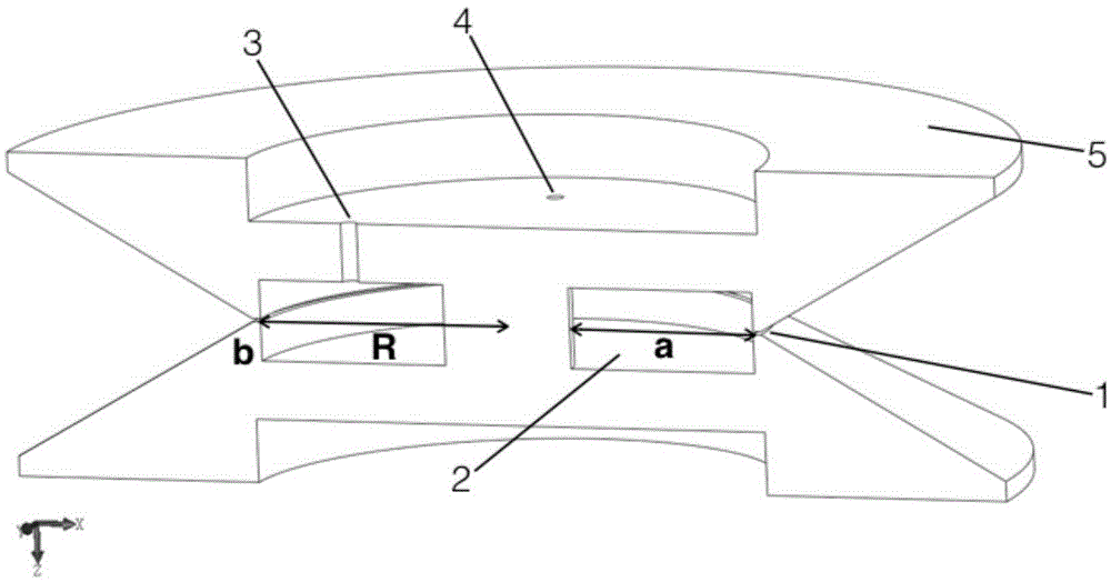
[0027]In the present invention, l=3 is selected, the radio frequency is 10 GHz, the wide side a of the rectangular waveguide is 23 mm, the narrow side b is 10 mm, and the circumference of the metal cavity is C=118.7 mm. At this time, the side slit circular ring will radiate electromagnetic waves to the space, forming a circular traveling wave antenna of a magnetic source.

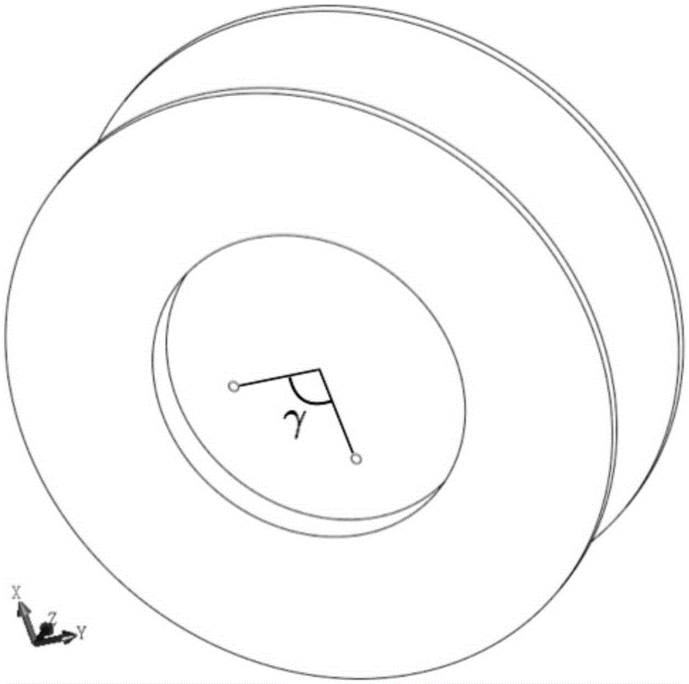
[0028] Figure 4 It is the electric field phase distribution diagram of the circular traveling wave antenna radiated in space obtained in the electromagnetic simulation software CST. It can be seen that the change of the electric field phase around the circular angle of the propagation direction presents a vortex characteristic, and the change of the electric field phase along the circle satisfies 2πl=6π, Such as Figure 6 As shown, this shows that the ring traveling wave antenna based on the metal ring cavity produces l=3 radio frequency OAM beams. Figure 5 It is the far-field pattern of the annular tra...


PUM


Abstract

The invention discloses an antenna for generating radial spreading RF OAM wave beams based on an annular travelling wave antenna. The integral structure of the antenna includes a metal annular cavity, a circular ring slit is formed in one side surface of the cavity, the metal annular cavity is formed by bending a rectangular waveguide, the width of the metal annular cavity serves as the broadside of the rectangular waveguide, the height of the side surface serves as the narrow side of the rectangular waveguide, the slit is arranged in the middle of the narrow side, the perimeter of the metal annular cavity equals the vertical length of the rectangular waveguide, the sidewall of the metal annular cavity is provided with an annular loudspeaker, the annular loudspeaker is composed of two parts in up and down symmetry, a slit is formed at the bottom end of the annular loudspeaker during combination, and the position of the slit corresponds to the circular ring slit in the middle of the narrow side of the annular metal cavity. The antenna structure of the invention is formed by combining a resonant cavity of the rectangular waveguide with the antenna structure of the annular travelling wave antenna, the channel capacity of a direct channel can be improved, the transmission distance is increased, and the transmission efficiency of the communication system is improved.

Description

technical field [0001] The invention belongs to the field of OAM wireless communication, and relates to an antenna for generating radially propagating radio frequency OAM beams based on an annular traveling wave antenna. Background technique [0002] The popularization of mobile Internet has made the wireless communication spectrum resources extremely tight, and there are a lot of gaps. The contradiction between the large-capacity requirements of mobile communication systems and the limited spectrum resources has become increasingly prominent. The spectrum resources of electromagnetic waves are very limited, and it is difficult to meet the new needs of wireless communication only by dividing new spectrums. However, capacity resources based on the conventional parameters of electromagnetic waves such as frequency spectrum, phase, and amplitude have been fully developed and utilized. Although the gradual expansion in these dimensions can continue, there is not enough room to ...

Claims


Application Information

Patent Timeline
IPC IPC(8): H01Q13/02H01Q13/20
Inventor 张倬钒郑史烈章献民金晓峰池灏
Owner ZHEJIANG UNIV
Why Eureka
Try Eureka