Multi-infeed-short-circuit-ratio-based dynamic reactive compensation point selection method

A multi-infeed short-circuit ratio and dynamic technology, applied in reactive power compensation, reactive power adjustment/elimination/compensation, etc., can solve problems that have not comprehensively considered the characteristics of multi-DC infeed system dynamic component model characteristics, etc.

Active Publication Date: 2016-02-24
CHINA ELECTRIC POWER RES INST +2
View PDF10 Cites 14 Cited by
  • Summary
  • Abstract
  • Description
  • Claims
  • Application Information

AI Technical Summary

Problems solved by technology
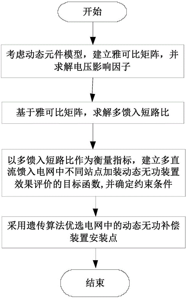
At present, the existing dynamic reactive power compensation device configuration methods at home and abroad are generally based on the weak area of ​​s...

Method used


Image

  • Multi-infeed-short-circuit-ratio-based dynamic reactive compensation point selection method
  • Multi-infeed-short-circuit-ratio-based dynamic reactive compensation point selection method
  • Multi-infeed-short-circuit-ratio-based dynamic reactive compensation point selection method

Examples


Embodiment 1

[0126] The point selection method provided by the present invention is applied to the current East China power grid to carry out the calculation of the multi-infeed short-circuit ratio. Assuming that the result obtained by using the traditional point selection method is MISCR p , the result obtained by the point selection method provided by the present invention is MISCR p '. The east China power grid feeds in 9 DC circuits, and the calculation results of the East China power grid’s DC multi-infeed short-circuit ratio in 2016 are shown in 1:

[0127] Table 1

[0128]

[0129] In Table 1, MISCR' does not consider the DC control mode, and the load model is "40% constant impedance + 60% constant power".

[0130] It can be seen from the results in the table that there are certain differences in the calculation results of the two methods, but the sorting according to the multi-infeed short-circuit ratio has basically not changed.

[0131] For the same 9 circuits of DC, calcu...

Embodiment 2

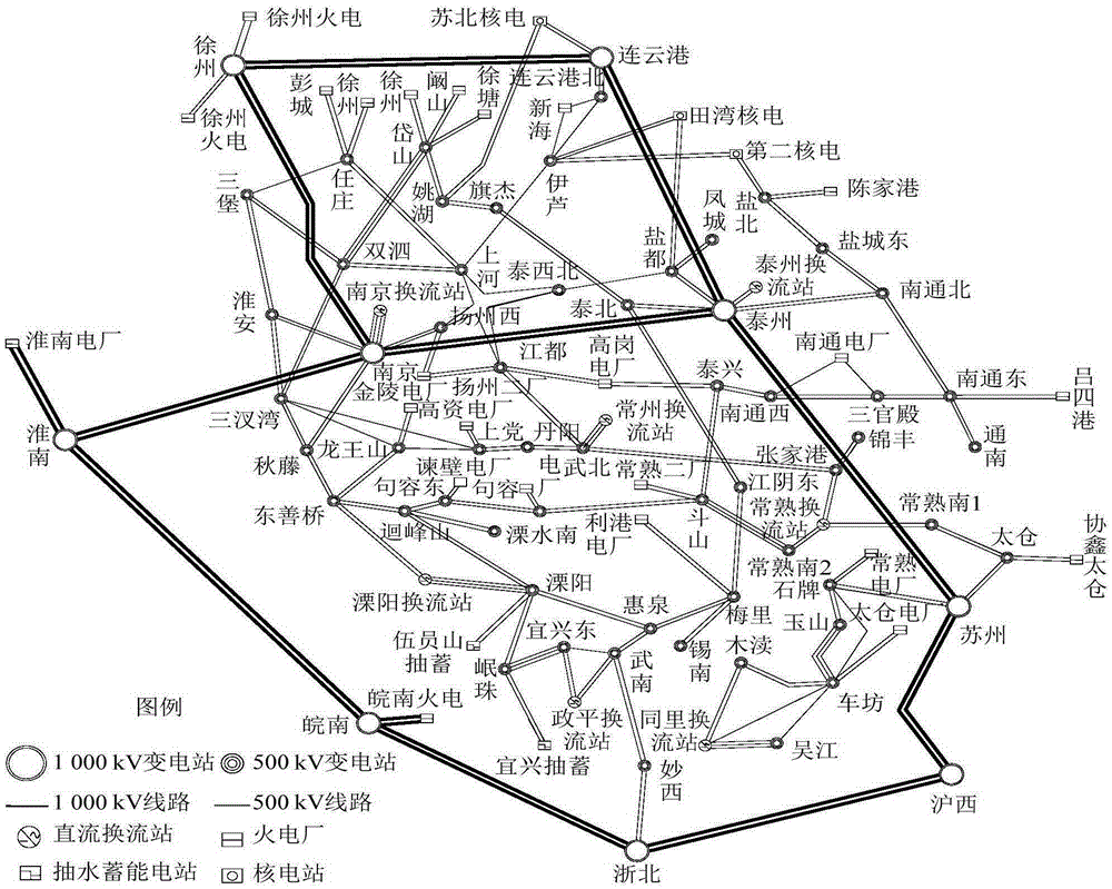
[0138] Apply the point selection method provided by the present invention to Jiangsu planning power grid in 2020, such as figure 2 As shown, there are 7 DC drop points in Zhengping, Tongli, Liyang, Taizhou, Nanjing, Changshu, and Changzhou, forming a typical multi-DC feed-in power grid, and Jiangsu power grid receives 40% of the electricity. Due to the large-scale feed-in DC, if no dynamic reactive power compensation device is installed, three-phase permanent short-circuit faults in 14 circuits of AC lines in Jiangsu will lead to voltage instability.

[0139] Select 25 500kV substations in southern Jiangsu as candidate sites, as shown in Table 3, select 5 sites to install SVCs with a capacity of 2×240Mvar through the optimization program;

[0140] table 3

[0141]

[0142]

[0143] Set different evolutionary algebra T and the number of individuals in the group M, and perform optimization calculations. The results of the dynamic reactive power compensation point selecti...


PUM


Abstract

The invention provides a multi-infeed-short-circuit-ratio-based dynamic reactive compensation point selection method. The method comprises the following steps: establishing a jacobian matrix and solving a voltage impact factor; determining a multi-infeed short circuit ratio according to the voltage impact factor; establishing effect evaluation objective functions of dynamic reactive compensation apparatus installation at all stations and corresponding constraint conditions; and selecting an optimal dynamic reactive compensation apparatus installation point by using a genetic algorithm. According to the invention, with consideration of the interactive influence between multi-loop direct-current lines, an effective method and an effective technical support are provided for selection of a dynamic reactive compensation apparatus installation point at a direct-current multi-infeed area of the country; and because the influences on the system stability by response characteristics of all elements during the dynamic process are taken into consideration, the point selection method is practical and has the engineering application value. Dynamic point selection optimization is carried out by using the genetic algorithm, so that the calculation efficiency is high.

Description

technical field [0001] The invention belongs to the technical field of power systems, and in particular relates to a dynamic reactive power compensation point selection method based on multi-infeed short-circuit ratios. Background technique [0002] The load center areas such as the Yangtze River Delta in East my country are limited by the development of local conventional power sources. In the future, there will be a multi-DC centralized feed-in structure. System failures may cause chain reactions of multiple DC circuits, causing voltage stability problems. The operation experience of power grids at home and abroad shows that dynamic reactive power compensation devices are ideal solutions for problems involving reactive power / voltage control. Dynamic reactive power compensation devices have flexible control strategies and fast response speeds. For voltage stability issues, dynamic reactive power compensation devices can be considered to improve the voltage support capabilit...

Claims


Application Information

Patent Timeline
IPC IPC(8): H02J3/18
CPCY02E40/30
Inventor 王雅婷张彦涛周勤勇张一驰
Owner CHINA ELECTRIC POWER RES INST
Why Eureka
Try Eureka