
Circular sawing machine for steel plate cutting

A circular saw and steel plate technology, applied in the field of steel plate cutting circular sawing machines, can solve the problems of at least several hours or even several days of waiting, the impact of sawing quality and productivity, and the impact on the production progress of the enterprise, achieving a high degree of automation, Long service life and high machining accuracy

Active Publication Date: 2016-03-02
江苏宁兴恒力智能设备有限公司
View PDF5 Cites 13 Cited by
  • Summary
  • Abstract
  • Description
  • Claims
  • Application Information

AI Technical Summary

Problems solved by technology

The band sawing machine can cut steel ingots with a thickness of 1m or more. It has its own technical advantages, but the cutting speed is slow and the efficiency is low. If the company needs it urgently, it will have to wait for several hours or even several days at least, which will affect the required business. production progress
[0003] For the production and use of most enterprises, the thickness of the steel plate used is not very thick. Generally, the thickness of the steel (die steel) used in the manufacture of molds is rarely required to exceed 100mm. At the same time, the strength and hardness of the mold steel are high. cutting, but sawing quality and productivity suffer

Method used


Image

  • Circular sawing machine for steel plate cutting
  • Circular sawing machine for steel plate cutting
  • Circular sawing machine for steel plate cutting

Examples


Embodiment Construction

[0029] The following descriptions are only preferred embodiments of the present invention, and therefore do not limit the protection scope of the present invention.

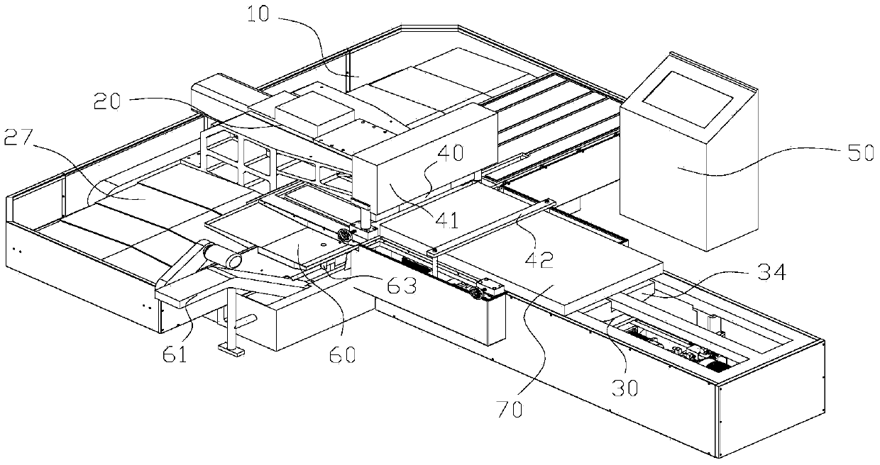
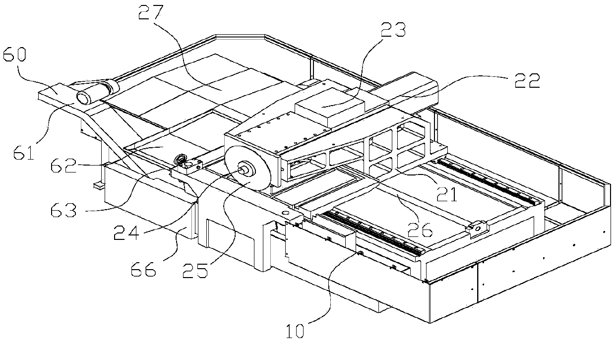
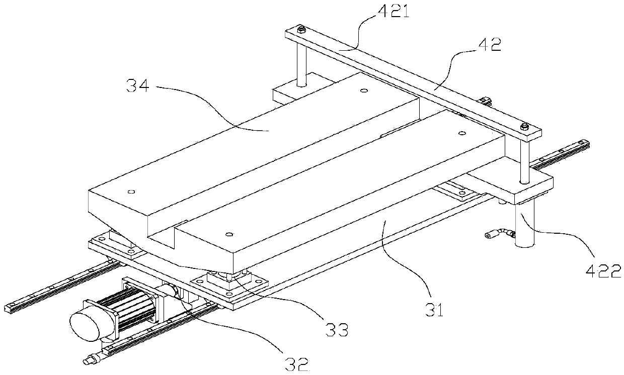
[0030] Examples, see Figure 1 to Figure 3 Shown: a steel plate cutting circular sawing machine, including a frame 10, a cutting device 20 installed on the frame 10, a moving assembly 30 for conveying a workpiece 70, a pressing assembly 40, and a control system 50, and the moving assembly 30 includes a moving plate 31 , the screw assembly 32 installed on one side of the moving plate 31, the telescopic assembly 33 installed on the other side of the moving plate 31 and the support plate 34 fixedly connected on the output shaft of the telescopic assembly 33, the pressing assembly 40 includes the main pressing Assembly 41 and auxiliary pressing assembly 42, the main pressing assembly 41 is pressed on the frame 10 and faces the cutting device 20, the auxiliary pressing assembly 42 is installed on the supporting plate ...


PUM


Abstract

The invention discloses a circular sawing machine for steel plate cutting. The circular sawing machine for steel plate cutting comprises a rack, a cutting device, a moving assembly, a pressing assembly and a control system, wherein the cutting device is mounted on the rack, and the moving assembly is used for conveying a workpiece. The moving assembly comprises a moving plate, a screw rod component, a telescopic component and a supporting plate, wherein the screw rod component is mounted on one side of the moving plate, the telescopic component is mounted on the other side of the moving plate, and the supporting plate is fixedly connected to an output shaft of the telescopic component. The pressing assembly comprises a main pressing component and an auxiliary pressing component. The main pressing component is pressed on the rack and faces the cutting device, and the auxiliary pressing component is mounted on the supporting plate. The workpiece is placed on the supporting plate. The control system controls the screw rod component to drive the moving plate to move and enables the pressing assembly to press the workpiece. The workpiece is cut by the cutting device. The circular sawing machine for steel plate cutting has the characteristics of being high in cutting efficiency and cutting precision.

Description

technical field [0001] The invention relates to the technical field of sawing, in particular to a circular sawing machine for cutting steel plates. Background technique [0002] At present, the main equipment for sawing steel plates is band sawing machine and bow sawing machine. The band sawing machine is used for sawing large steel plate raw materials with large area and thickness, dividing it into workpiece blanks required for production or providing blanks for bow sawing machine processing; bow sawing machine is mainly used for sawing small-sized block workpiece blanks or Sawing of profiles. The band sawing machine can cut steel ingots with a thickness of 1m or more. It has its own technical advantages, but the sawing speed is slow and the efficiency is low. If the enterprise needs it urgently, it will have to wait for several hours or even several days at least, which will affect the required enterprises. production progress. [0003] For the production and use of mos...

Claims


Application Information

Patent Timeline
Patent Type & Authority Applications(China)
IPC IPC(8): B23D47/04B23D59/02B23D47/02B23Q11/06B23Q7/06
Inventor 周斌王文彤杨韵沃勤昌杨超珍
Owner 江苏宁兴恒力智能设备有限公司
Learn More