Steel bar lap joint structure containing FRP constraint ring

A technology of lap connection and confinement ring, which is applied to the connection of steel bars in concrete structures and the field of steel bar lap connection structures, can solve problems such as high requirements for construction and installation accuracy, impact on production efficiency, weakened energy dissipation capacity of connection position deformation, etc., to achieve Low requirements for construction and installation accuracy, reliable and stable connection performance, and easy to guarantee construction quality

Inactive Publication Date: 2016-03-02
SHENYANG JIANZHU UNIVERSITY
View PDF6 Cites 7 Cited by
  • Summary
  • Abstract
  • Description
  • Claims
  • Application Information

AI Technical Summary

Problems solved by technology

[0003] Disadvantages of the sleeve: 1. High precision requirements for construction and installation. Since the connection adopts a butt joint and non-lap joint method, the connection distance is short, and the connection quality is difficult to guarantee (in terms of domestic construction conditions); 2. The rigidity of the sleeve connection part is too large, The plastic hinge area moves up and decreases, which weakens the deformation energy dissipation capacity of the connection position; 3. The amount of steel used for the sleeve is large, the price is expensive, and the economy is not good
4. Higher requirements for grouting materials, which increases the cost
[0004] Disadvantages of constrained grout-anchor lap connection: 1. The hole-forming technology is immature, which has a great impact on production efficiency; 2. The grouting material directly contacts the concrete hole wall to absorb water, resulting in difficulty in grouting; 3. The quality of the hole is not easy to guarantee, and most holes The concrete of the inner wall is cracked, affecting the durability of the structure

Method used


Image

  • Steel bar lap joint structure containing FRP constraint ring
  • Steel bar lap joint structure containing FRP constraint ring
  • Steel bar lap joint structure containing FRP constraint ring

Examples


Embodiment

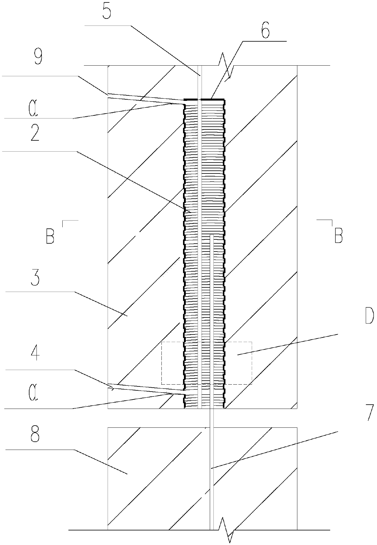
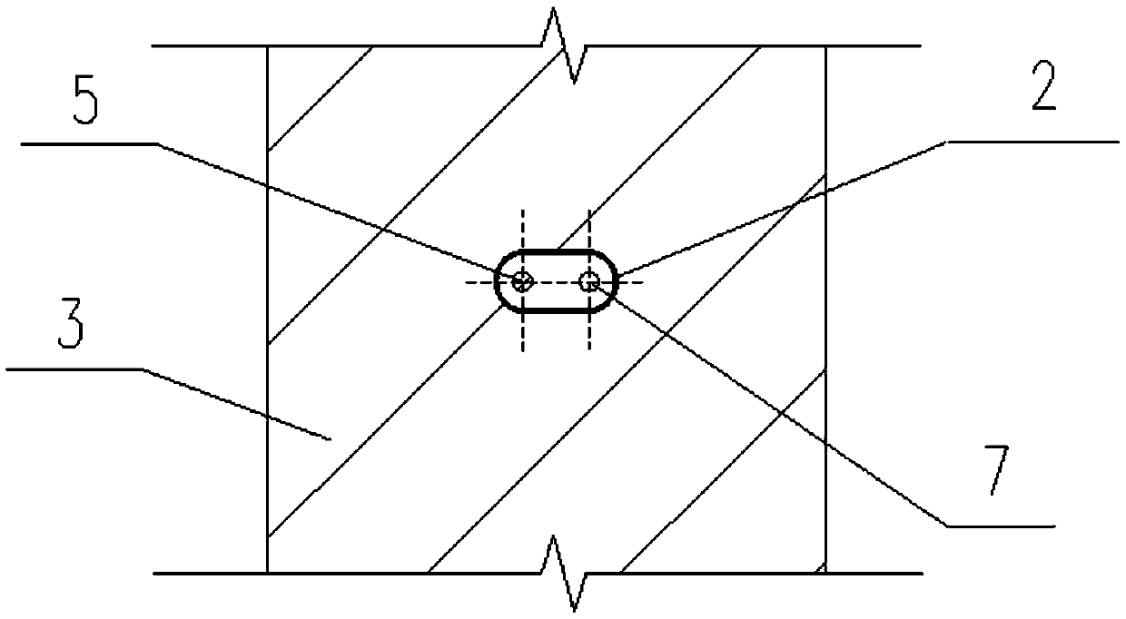
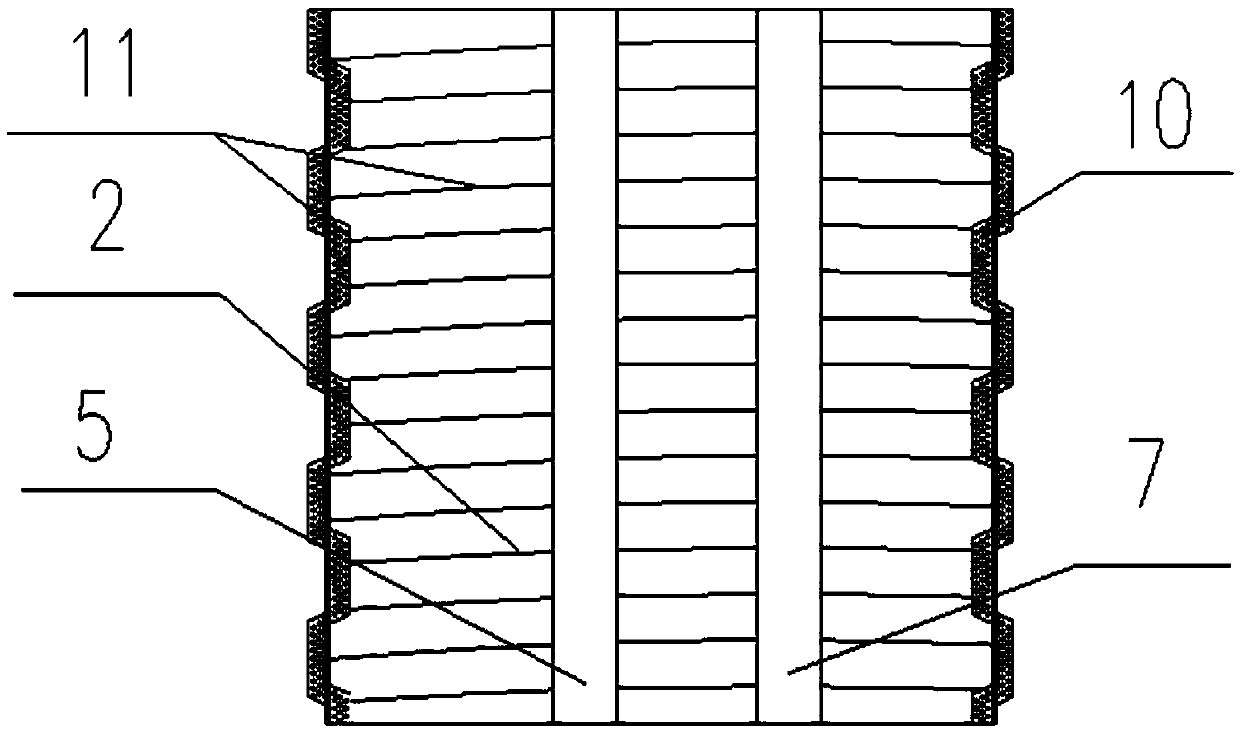
[0030] Example: such as figure 1 , figure 2 As shown, the present invention includes an upper prefabricated component 3, a lower prefabricated component 8, a FRP restraint ring 2, a pre-embedded steel bar 5 and an outstretched connecting steel bar 7, and an FRP restraint ring 2 is arranged inside the lower end of the upper prefabricated component 3, and the FRP restraint ring 2 There is a grouting hole 4 at the lower end, a grouting hole 9 at the upper end, and a sealing elastic rubber sealing ring 6 with a round hole at the top of the FRP confinement ring 2 to prevent the entry of concrete mortar, etc.; The steel bar 5 extends into the FRP confinement ring 2 through the round hole of the sealing ring 6, and the externally extending connecting steel bar 7 in the lower prefabricated component 8 protrudes into the FRP confinement ring 2 to form an overlap with the pre-embedded steel bar 5 in the upper prefabricated component 3 For connection, the expansion grouting material is...


PUM


Abstract

A steel bar lap joint structure containing an FRP constraint ring belongs to the technical field of the concrete member. The joint structure includes an upper layer prefabricated component, a lower layer prefabricated component, an FRP constraint ring, a pre-embedded steel bar and a protruding connection steel bar. The FRP constraint ring is arranged in the lower end of the upper layer prefabricated component; the lower part of the FRP constraint ring is provided with a grouting hole, and the upper part of the FRP constraint ring is provided with a discharging hole; the top end of the FRP constraint ring is provided with a sealing elastic rubber sealing ring with a round hole; the pre-embedded steel bar of the upper layer prefabricated component passes through the round hole on the sealing ring and extends into the FRP constraint ring; the protruding connection steel bar in the lower prefabricated component extends into the FRP constraint ring to form lap joint with the pre-embedded steel bar in the upper layer prefabricated component; and an expansion grouting material is grouted along the grouting hole of the FRP constraint ring to fill the FRP constraint ring, so as to form an assembled monolithic joint structure. The steel bar lap joint structure provided by the invention has the advantages of reliable and stable joint performance, low cost, low precision requirement for on-site installation and easily guaranteed construction quality.

Description

technical field [0001] The invention belongs to the technical field of concrete components, in particular to a steel bar lap connection structure with FRP restraint rings. It is specifically suitable for the connection of steel bars in concrete structures, especially for the connection of steel bars in prefabricated concrete components for residential industrialization. Background technique [0002] At present, the technical system of connection in domestic prefabricated prefabricated concrete structures is mainly based on sleeve connection and grout anchor lap connection. The sleeve is divided into two types: full grout sleeve and half grout sleeve, the connection methods are mechanical connection. [0003] Disadvantages of the sleeve: 1. High precision requirements for construction and installation. Since the connection adopts a butt joint and non-lap joint method, the connection distance is short, and the connection quality is difficult to guarantee (in terms of domestic...

Claims


Application Information

Patent Timeline
Patent Type & Authority Applications(China)
IPC IPC(8): E04C5/16
CPCE04C5/163
Inventor 金峤温学彬李明王建超高猛李哲王传克
Owner SHENYANG JIANZHU UNIVERSITY
Why Eureka
Try Eureka