Drill pipe quick-connecting mechanism

A quick connection and drill pipe technology, which is applied in the direction of drill pipe, drill pipe, drilling equipment, etc., can solve the problems of increasing the cost of exploration and development, reducing the service life of drill pipe, deformation and damage of drill pipe, etc., and achieves compact structure, improved The effect of service life and increasing the force bearing area

Inactive Publication Date: 2016-03-02
CHINA UNIV OF GEOSCIENCES (WUHAN)
View PDF9 Cites 1 Cited by
  • Summary
  • Abstract
  • Description
  • Claims
  • Application Information

AI Technical Summary

Problems solved by technology

The above drill pipe connection structures all use pin-type connections, but geological drill pipes are designed for lightness, and the wall thickness of the drill pipe is often designed to be small. The use of pin...

Method used


Image

  • Drill pipe quick-connecting mechanism
  • Drill pipe quick-connecting mechanism
  • Drill pipe quick-connecting mechanism

Examples


Embodiment 1

[0021] Embodiment 1: A drill pipe quick connection mechanism provided by the present invention is provided with a lower joint 2 , an O-ring 3 and an upper joint 4 . Its overall assembly structure is as figure 1 As shown, the assembly sequence is the lower drill pipe 1, the lower joint 2, the upper joint 4 and the upper drill pipe 5, and the O-ring 3 is installed in the sealing groove 8 of the upper joint for sealing between the upper joint and the lower joint.

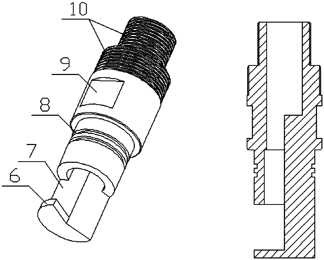
[0022] Such as figure 2 as shown, figure 2 It is a schematic diagram of the three-dimensional structure and cross-sectional structure of the upper joint of the present invention, the upper end of the upper joint 4 is provided with an upper joint thread 10, and the upper joint thread is used to connect with the upper drill pipe 5, and the middle part of the upper joint is provided with an upper joint flat groove 9 and the upper joint sealing groove 8, the lower part of the upper joint is provided with an upper joint...

Embodiment 2

[0027] Embodiment 2: The quick connection mechanism for drill rods provided in Embodiment 1 is applied to a knapsack drilling rig, which can realize rapid variable-diameter connection to form drill rods of two specifications, and can easily disassemble the drill rods of the knapsack drilling rig. Pack.

[0028] The specific operation process is:

[0029] 1. When the upper drill pipe 5 is a large-diameter drill pipe, the upper joint 4 is connected to the upper drill pipe 5 through the large-diameter thread part at the rear end of the upper joint thread 10; when the upper drill pipe 5 is a small-diameter drill pipe, only use The small-diameter threaded connection of the small-diameter drill pipe at the front end in the upper joint thread 10 just can complete the quick connection of the drill pipe.

[0030] 2. Install the O-ring 3 in the sealing groove 8 of the upper joint, insert one end of the upper joint 4 with the O-ring installed into the lower joint 2 and screw it in until...


PUM


Abstract

The invention relates to a drill pipe quick-connecting mechanism comprising an upper joint, a lower joint, and an O-shaped ring. The O-shaped ring is installed in an upper joint sealing slot and used for sealing the upper joint and the lower joint. The upper joint and an upper drill pipe are in threaded connection, and the lower joint and a lower drill pipe are in threaded connection. The upper joint thread of the upper joint can be of two different apertures and can be connected with drill pipes of two different apertures, and therefore, quick connection with drill pipes of two specifications is realized. When the upper joint and the lower joint are connected, the side of an upper joint stopper and the side of a lower joint stopper contact each other. When rotating, the upper joint transfers torque to the lower joint through contact of the two sides. An upper joint axial block piece contacts the end face of the lower joint stopper, and bears the axial tension during drill pipe lifting. The mechanism of the invention has the characteristics of compact structure, good sealing performance, large stress area, long service life, convenient disassembly, and the like. The problem that a drill pipe is complex and cumbersome in disassembly and is easy to deform and damage previously is well solved.

Description

technical field [0001] The invention relates to a quick connection mechanism for drill pipes, specifically a mechanism that can be used for quick connection of drill pipes of the same specification and for quick connection of drill pipes of different specifications, and is especially suitable for backpack drilling rigs that require variable diameters. The quick connection belongs to the field of geological exploration. Background technique [0002] In the process of resource exploration and development, the drilling work of the drilling rig requires frequent unscrewing and unloading of the drill pipe, which is complicated, time-consuming and labor-intensive. In the Chinese utility model patent CN202882905U, a portable geological exploration sampling drilling rig is disclosed, in which the connection of the drill pipe adopts the structure of a pull-out pin shaft, which can reduce the workload of unscrewing the drill pipe; in the Chinese utility model patent CN2552937Y, it dis...

Claims


Application Information

Patent Timeline
IPC IPC(8): E21B17/042E21B17/043
CPCE21B17/0423E21B17/043
Inventor 李波张东霄赵海侗王锡霖张萌徐凯
Owner CHINA UNIV OF GEOSCIENCES (WUHAN)
Why Eureka
Try Eureka