CO2 drive flow rate monitoring method

A technology of flow monitoring and volume flow, which is used in measurement, production of fluids, and earth-moving drilling, etc., and can solve problems such as excessive flow interpretation deviation.

Active Publication Date: 2016-03-02
CHINA PETROLEUM & CHEM CORP +1
View PDF8 Cites 2 Cited by
  • Summary
  • Abstract
  • Description
  • Claims
  • Application Information

AI Technical Summary

Problems solved by technology

[0004] The purpose of the present invention is in order to solve the existing CO 2 In the process of flow interpretation, the pressure difference is used to convert the fluid density, and the CO flow spectrum interpretation model is directly used to deal with CO 2 The flow spectrum leads to the defect that the flow interpretation is too large, and then a CO 2 Flood flow monitoring method

Method used


Image

  • CO2 drive flow rate monitoring method
  • CO2 drive flow rate monitoring method
  • CO2 drive flow rate monitoring method

Examples


Embodiment 1

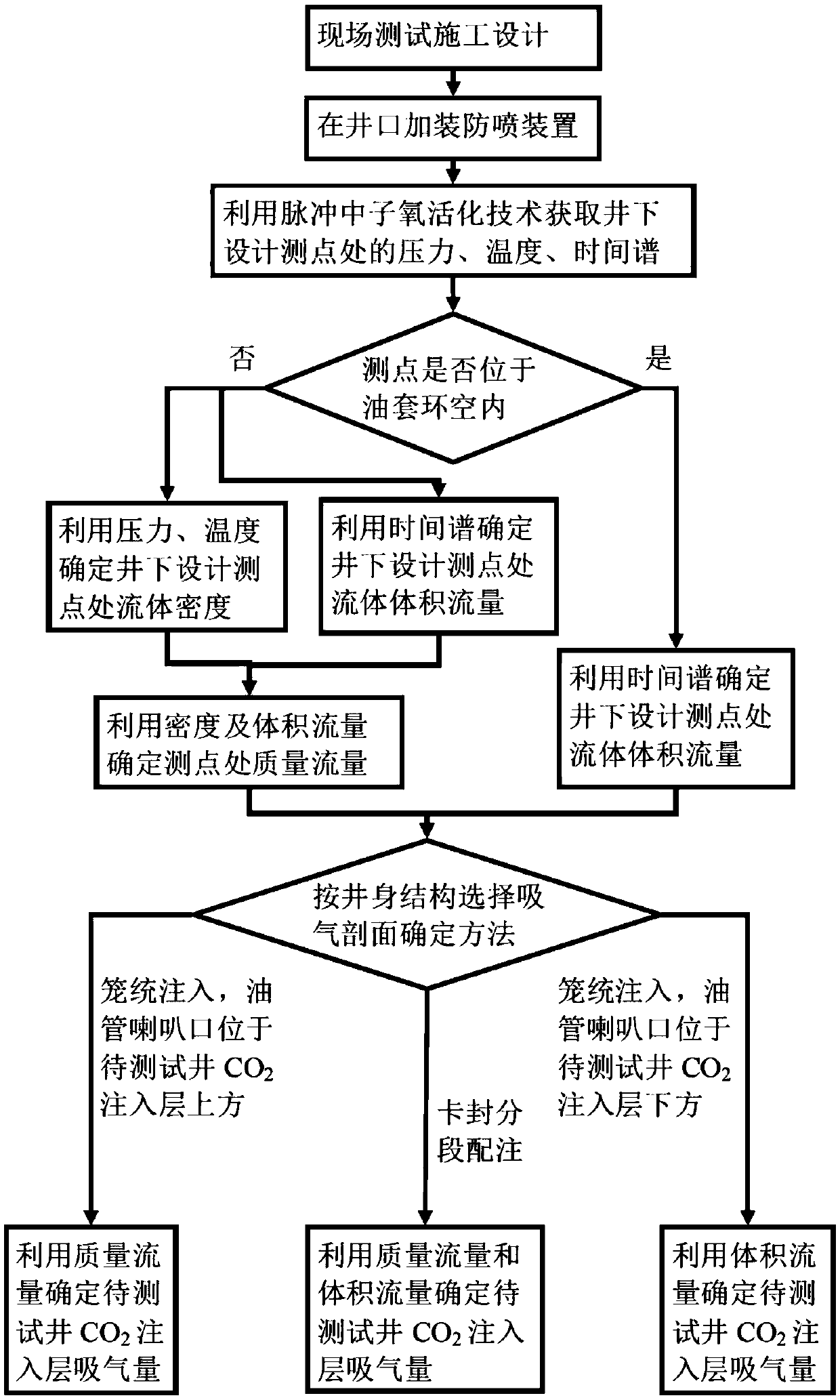
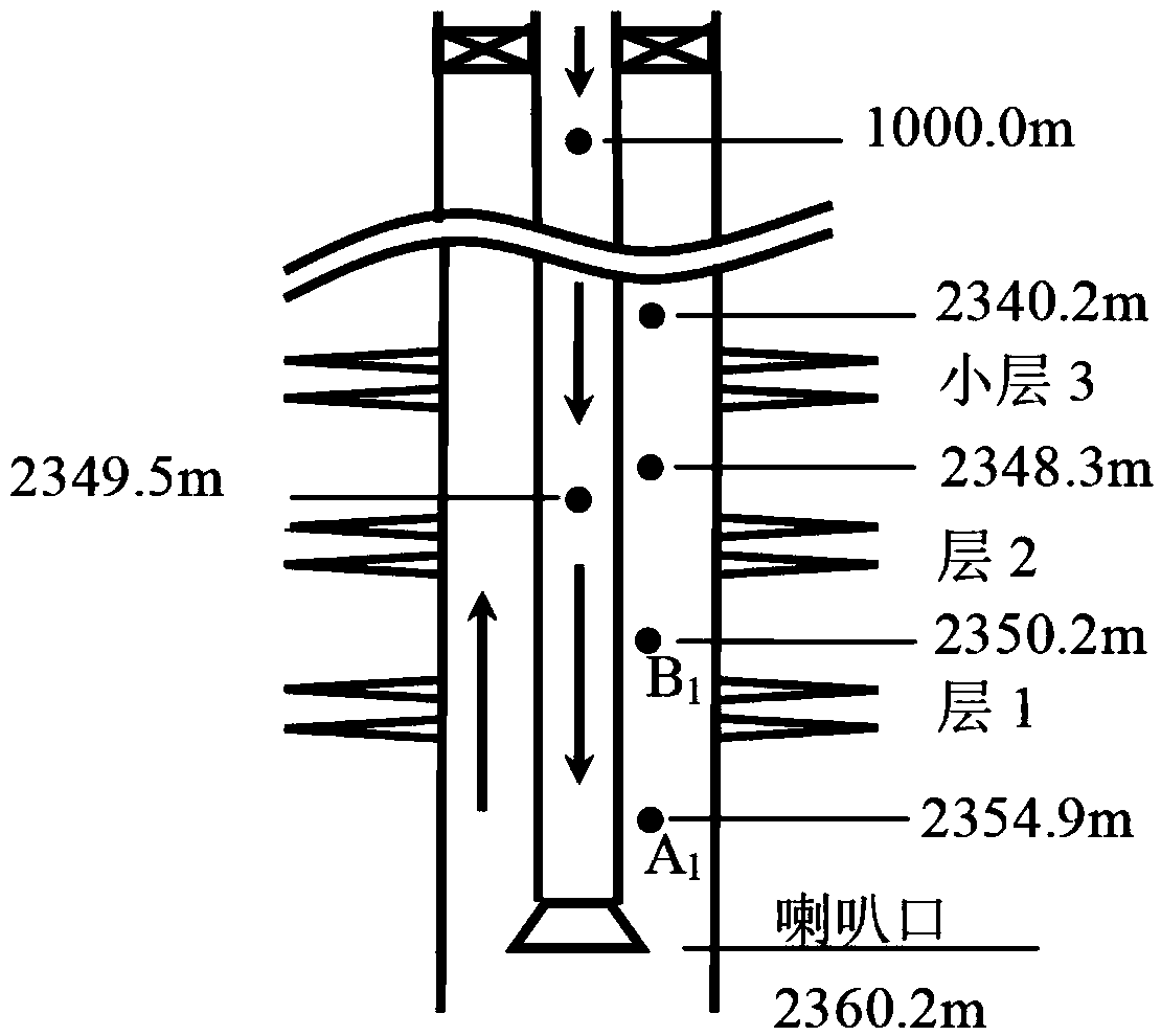
[0051] 1. Measuring point design of the well to be tested. Taking Well P1 in Zhongyuan Oilfield as an example, according to figure 1 The steps shown are processed, the well string structure and design measuring points are as follows figure 2 As shown, the well is a general injection method, injecting CO from the tubing 2 , the bell mouth of the tubing is below the perforated layer, the solid circles indicate the location of the measuring points, and the arrows indicate the direction of fluid flow. The basic conditions of the well and the design of the measuring points are shown in Table 1.

[0052] Table 1 Basic information of well P1

[0053]

[0054] 2. Install wellhead blowout preventer for the well to be tested.

[0055] A double-wing blowout preventer is installed at the wellhead, and a blowout preventer is installed on the double-wing blowout preventer, and a blowout preventer is installed on the blowout preventer, and the blowout preventer is equipped with a logg...

Embodiment 2

[0086] 1. Measuring point design of the well to be tested. Taking Well P2 of Zhongyuan Oilfield as an example, according to figure 1 The steps shown are processed, the well string structure and design measuring points are as follows Figure 6 As shown, the well is a general injection method, injecting CO from the tubing 2 , the bell mouth of the tubing is above the perforated layer, the solid circles indicate the location of the measuring points, and the arrows indicate the direction of fluid flow. The basic conditions of the well and the design of the measuring points are shown in Table 5.

[0087] Table 5 Basic Conditions of Well P2

[0088]

[0089] 2. With reference to steps 2-5 in Example 1, the monitoring parameters of each design measuring point are processed to determine the mass flow rate Q m,i and volume flow Q V,i (i=1,2,...,5), as shown in Table 6:

[0090] Table 6 Interpretation flow rate of each design measuring point in Well P2

[0091]

[0092] 3. A...

Embodiment 3

[0102] 1. Measuring point design of the well to be tested. Taking Well P3 in Zhongyuan Oilfield as an example, according to figure 1 The steps shown are processed, the well string structure and design measuring points are as follows Figure 7 As shown in Fig. 1, the well is injected with CO2 from the tubing in the way of sealing and segmental injection. 2 , the relative positions of the dispenser, design measuring point, and perforation sublayer are marked in the figure, and the depths of the dispenser and design measuring point are given. The solid circles represent the measuring points, and the packing Section 1 is between packer 2 and section 2 is between packer 2 and the well bottom. The basic situation and measuring point design of the well are shown in Table 8.

[0103] Table 8 Basic information of Well P3

[0104]

[0105] 2. With reference to steps 2-5 in Example 1, the monitoring parameters of each design measuring point are processed to determine the mass flow...


PUM


Abstract

The invention relates to a CO2 drive flow rate monitoring method, and belongs to an oilfield development input profile monitoring method. The CO2 drive flow rate monitoring method comprises the following steps that (1) measuring points of a to-be-tested well are designed; (2) a wellhead blowout prevention device is additionally arranged at the to-be-tested well; (3) monitoring parameters of the to-be-tested well are acquired; (4) the monitoring parameters of a certain designed measuring point acquired in the step (3) are processed, a mass flow rate Qm,1 or a volume flow rate QV,1 corresponding to the measuring point is determined; (5) according to the step (4), the monitoring parameters of the remaining designed measuring points are processed, a mass flow rate Qm,i or a volume flow rate QV,i corresponding to the i-th measuring point is determined; and (6) according to a tubular column structure and the step (4) and (5), the suction quantity of a CO2 input layer of the to-be-tested well is determined. With the adoption of a pulse neutron oxygen activation technology, CO2 flow rates of multiple runners of a CO2 injection well are determined, and a CO2 suction quantity interpretation model of a perforation layer is constructed according to the tubular column structure, so that the interpretation precision is higher, and support is provided for optimization of a CO2 drive development program.

Description

technical field [0001] The present invention relates to CO 2 The invention discloses a flooding flow monitoring method, which belongs to the monitoring method of an injection profile in oil field development. Background technique [0002] CO 2 Flooding is one of the effective means to enhance oil recovery in high water-cut reservoirs, and has attracted the attention of many oilfields in China. Conventional downhole fluid flow monitoring technologies include turbine flowmeters, radioisotope tracer methods, thermal tracer methods, electromagnetic flowmeters, and pulsed neutron oxygen activation logging techniques. 2 The fluid has changes in phase and density in the wellbore, and it is not a conductor, which leads to the following problems: the response law of the turbine flowmeter is complex and unstable; the radioactive isotope tracer cannot be effectively suspended in the fluid; the thermal tracer method logging response The signal is weak and the response law is unstable...

Claims


Application Information

Patent Timeline
Patent Type & Authority Applications(China)
IPC IPC(8): E21B47/00E21B47/06E21B47/07E21B43/16
CPCE21B43/164E21B47/00E21B47/06E21B47/07
Inventor 董勇吕清河李宏魁罗庆蒋国栋贾慧丽黄华张立
Owner CHINA PETROLEUM & CHEM CORP
Why Eureka
Try Eureka